GRBL firmware is used to control CNC machines with control electronics usually based on the ATmega328P processor. The most common setup is an Arduino UNO or a similar board built around this processor. GRBL is available both as source code and as a precompiled HEX file. This guide focuses on the precompiled 1.1 version, but the workflow is usable with small differences for other versions as well.
Firmware Download
The firmware can be downloaded for free from GitHub. There you can choose the required version and whether you want the precompiled HEX file or the source code. This guide uses the HEX version.
Firmware Installation
The procedure is described using an Arduino UNO, because it is very common. You can also use an Arduino NANO, MINI, or a standalone ATmega328P processor in your own application. There are also ready-made CNC controller boards designed directly for GRBL.
To upload the HEX firmware to Arduino UNO, use XLoader. Select the HEX file, the target board and the COM port, then upload the firmware to the board.
Firmware Configuration
After the firmware is uploaded successfully, the machine-specific parameters must be configured. Every CNC machine is different, so the firmware settings need to match the mechanics of the machine. The example uses a CNC Shield v3 expansion board and a portal milling machine.
First, you need to know the parameters of the electronics. CNC Shield boards allow microstepping configuration for the stepper drivers. Depending on the driver, the range can go from full step up to 128 microsteps. Common A4988 drivers support up to 16 microsteps, while DRV8825 drivers support up to 32 microsteps. For a CNC milling machine it is usually better to choose lower microstepping values, because motor torque drops as microstepping increases.
| Microsteps | 8 in the example, available range depends on the driver. |
|---|---|
| Motor steps per revolution | 200 for a common 1.8 degree stepper motor. |
| Lead screw pitch | 8 mm per revolution in the example machine. |
| Steps per millimeter | 8 x 200 / 8 = 200 steps per 1 mm. |
Configuration Options
GRBL can be configured in three basic ways: by editing the source code before compilation, through a serial terminal, or by using a configuration tool. Since this guide works with a precompiled firmware file, the configuration is stored in the processor EEPROM after upload.
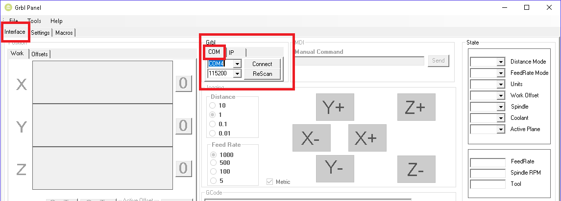
The guide uses GrblPanel, which can also be used later to control the CNC machine. Select the COM port, set the communication speed to 115200 bps and press Connect.
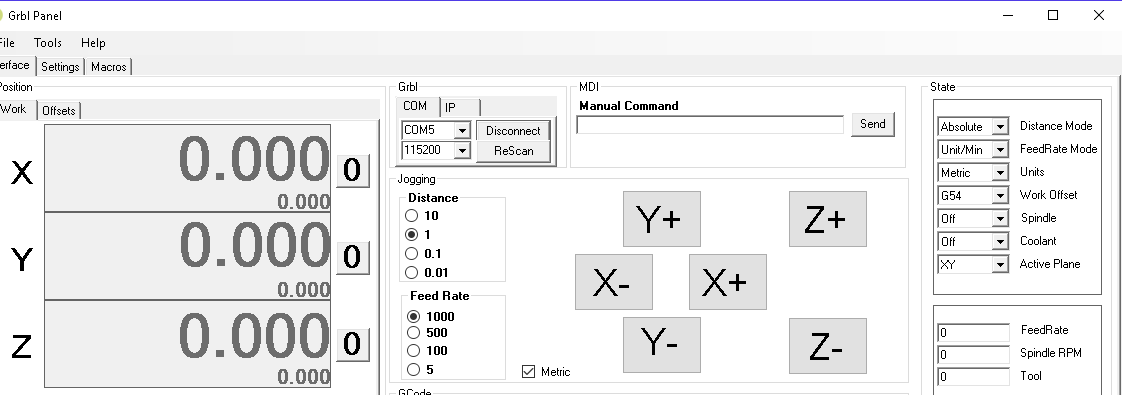
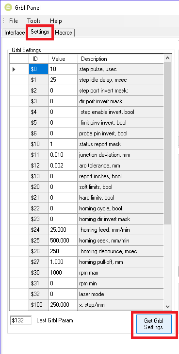
After a successful connection, switch to the Settings tab and use Get Grbl Settings to read all values. The table contains ID, Value and Description columns. The value can be edited by clicking into the Value field and saved with Enter.
Important GRBL Parameters
The following list covers the most important settings. GRBL contains more parameters, including control values used by the sender software. For the complete reference, see the official GRBL configuration documentation.
$0 – Step pulse, microseconds
Default value is 10. This setting depends on the stepper driver and defines the minimum step pulse length. In practice it usually does not need to be changed, but excessive values can cause motion problems.
$1 – Step idle delay, sec
Default value is 25 in the 1 to 255 range. It controls the delay before motors are disabled after motion stops. For CNC machines it is often useful to set this value to 255 so that the motors stay powered and hold their position.
$2 – Step port invert mask
Default value is 0 in the 0 to 7 range. This setting inverts STEP signals for individual axes. The value written to firmware is taken from the Setting Value column.
| Setting Value | Mask | Invert X | Invert Y | Invert Z |
|---|---|---|---|---|
| 0 | 00000000 | N | N | N |
| 1 | 00000001 | Y | N | N |
| 2 | 00000010 | N | Y | N |
| 3 | 00000011 | Y | Y | N |
| 4 | 00000100 | N | N | Y |
| 5 | 00000101 | Y | N | Y |
| 6 | 00000110 | N | Y | Y |
| 7 | 00000111 | Y | Y | Y |
$3 – Direction port invert mask
Default value is 0 in the 0 to 7 range. It inverts DIR signals for axes. Use the same mask table as for $2. For example, to reverse the Y axis, enter value 2.
$4 – Step enable invert
Default value is 0. It inverts the driver enable logic. With common drivers this usually does not need to be changed.
$5 – Limit pins invert
Default value is 0. It inverts limit switch logic. A change can require a controller restart.
$6 – Probe pin invert
Default value is 0. It works like the limit input inversion, but for the Z probe input.
$10 – Status report mask
This setting defines what real-time data is reported back to the sender software. More reported data can increase communication load, so use only what is needed.
| Report Type | Value |
|---|---|
| Machine Position | 1 |
| Work Position | 2 |
| Planner Buffer | 4 |
| RX Buffer | 8 |
| Limit Pins | 16 |
To report Machine Position and Work Position, enter value 3, which is the sum of both selected values.
$11 – Junction deviation
Default value is 0.010 mm. It affects how the machine slows down before direction changes. Higher values allow faster cornering; lower values reduce the risk of lost steps. A useful explanation is available in Improving GRBL cornering algorithm.
$12 – Arc tolerance
Default value is 0.002 mm. It controls the accuracy of arc interpolation. Lower values can improve precision but increase calculation load.
$13 – Report inches
Default value is 0. Value 0 reports millimeters, value 1 reports inches.
$20 – Soft limits
Enables software travel limits. Homing, axis travel values and reference switches must be configured correctly before using this feature.
$21 – Hard limits
Enables physical limit switches. Triggering any switch stops the machine immediately and raises an alarm. Inputs should be protected against noise.
$22 – Homing cycle
Enables the homing cycle. When enabled, the machine should be referenced after startup.
$23 – Homing dir invert mask
Defines homing direction for each axis. The same mask logic as parameter $2 is used.
$24 – Homing feed
Final slow approach speed during homing after the switch has been found.
$25 – Homing seek
Initial speed used while searching for the homing switch.
$26 – Homing debounce
Debounce time for mechanical switches. A typical practical value is around 10 to 30 ms.
$27 – Homing pull-off
Distance the axis moves away from the switch after homing, preventing accidental limit activation.
$100, $101 and $102 – X, Y and Z steps per millimeter
One of the most important settings. It defines how many motor steps are needed for 1 mm of travel on each axis.
$110, $111 and $112 – maximum axis rate
Maximum speed of each axis. The value must match the machine mechanics, motors, drivers and supply voltage.
$120, $121 and $122 – axis acceleration
Acceleration of each axis. Test every axis separately and keep a reasonable safety reserve below the limit where steps are lost.
$130, $131 and $132 – maximum axis travel
Defines the working area of each axis and is used by soft limits. Homing must be configured correctly for this to work reliably.
These values are a practical introduction, not a replacement for the full documentation. Always verify the settings against the official Configuring GRBL documentation and tune them for your exact machine.
Documentation
The original PDF guide and the discussion thread are available below.