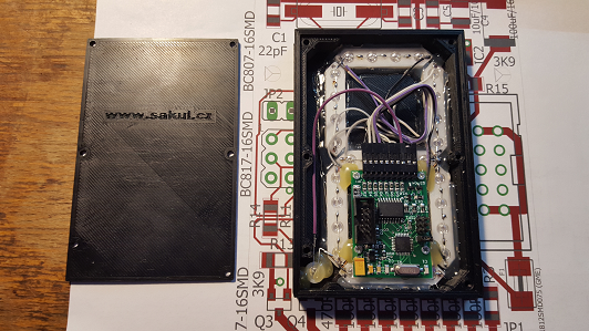
This display module was created as a successor to all previous display modules for large displays. It uses a more powerful processor, which made it possible to add more functions and, mainly for the future, firmware updates through a simple application. The display module can now communicate with the outside world, change its configuration through commands and report operating data back.
Technical Specifications
| Supply voltage | 12 V/DC |
|---|---|
| Current consumption | approx. 200 mA, depending on the LEDs used, maximum 0.5 A |
| Communication interface | UART configurable by AT commands, default speed 19.2 kb/s |
| Displayed characters | 16 characters: blank, 0-9, -, L, P, E, U. Applies to the basic version. |
| Number of addresses | 16 in the basic version |
| Brightness control | PWM |
| Configuration | AT commands and jumper links |
| Voltage measurement | 5-15 V |
| Dot control | Separate decimal point on the display module and output for colon dots |
Construction Description
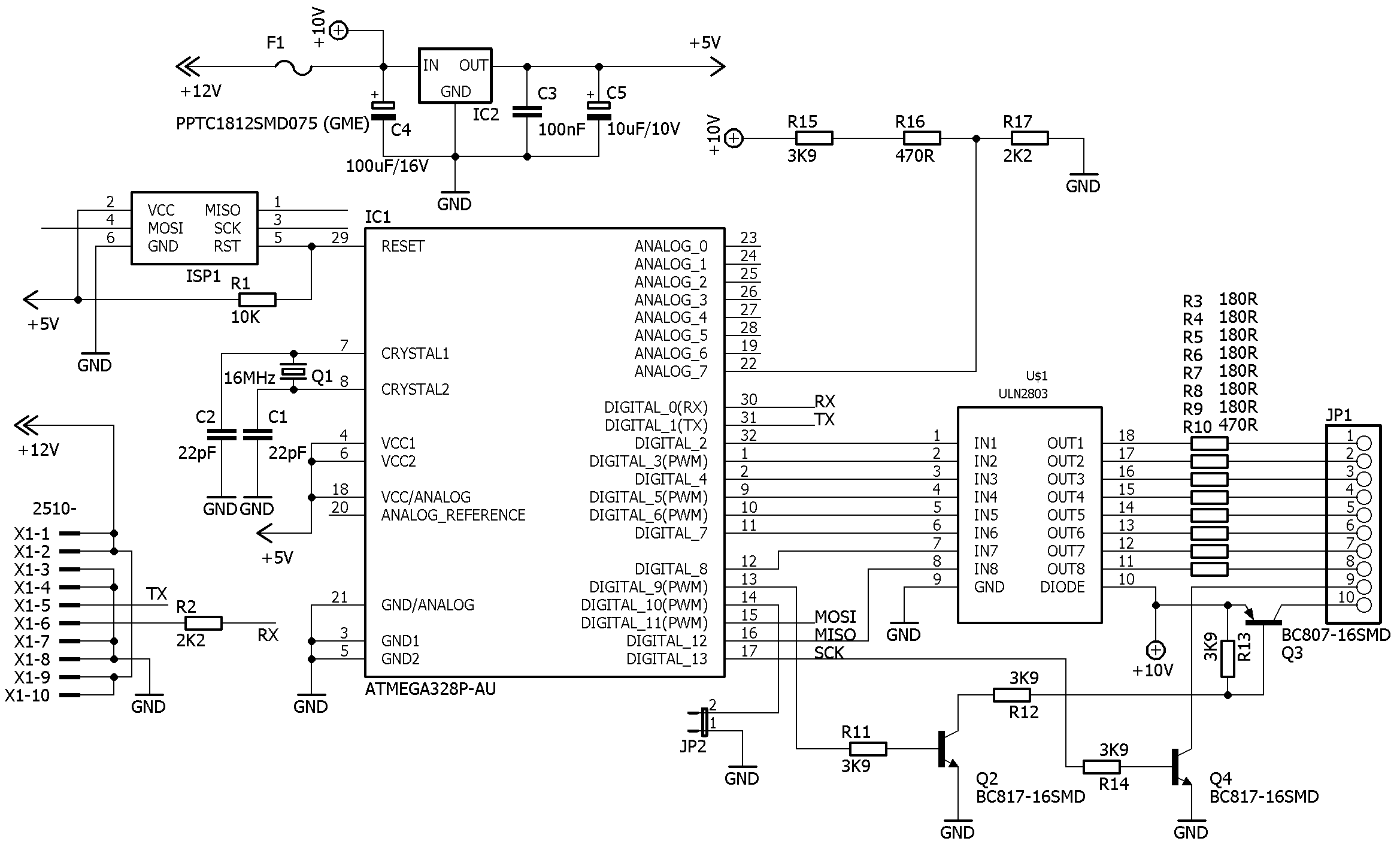
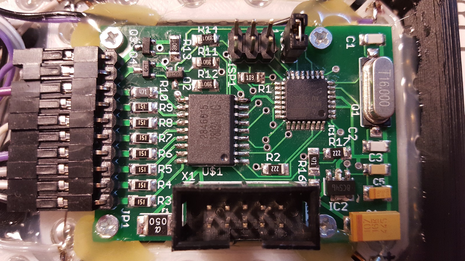
As mentioned in the introduction, this is a successor to the previous display modules for large displays. Backward compatibility with the previous modules was preserved, so a large display assembled from these modules can still be connected to older constructions. On the other hand, using the ATMEGA328P processor significantly expanded the possibilities of this display module. The circuit itself did not change too much. The heart of the circuit is processor IC1, which communicates with the outside world through the UART interface brought out to connector X1. It is important to note that the pinout of this connector was changed compared with previous versions and is not backward compatible. The supply pins were rearranged to reduce the risk of failure caused by an incorrectly connected connector and, at the same time, to increase the current capability of the whole bus. A TX channel from the processor was also added for bidirectional communication with a master application. The power supply circuit was supplemented with resettable fuse F1, which should protect the electronics in case of a short circuit on the connected display element, such as LEDs, LED strips, LED displays and similar loads. Supply-voltage detection was also added using a divider made from resistors R15-R17. The power output for driving the display element was slightly changed as well. The original seven-port driver was replaced by eight-port driver US1. Colon control was kept through transistor Q4. Brightness control through transistors Q2 and Q3 was added and is implemented by PWM.
Because most settings can be adjusted with AT commands, the DIP switch was no longer needed and jumper link JP2 was used instead. This jumper selects the communication protocol. When it is fitted, the old protocol is used; it is compatible with older constructions and uses a one-byte protocol. When it is not fitted, the new protocol is used.
Connector ISP1 contains all signals required for programming the processor. It also includes one pin for selecting the default setting. If the MOSI pin is grounded during startup, the default communication speed is set to 19.2 kb/s. Connector JP1 is used to connect a common-anode display element.
Schematic
Assembly Plan
PCB Drawing
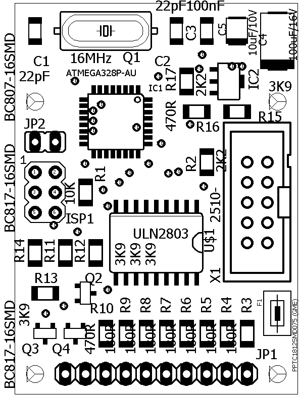
I do not include PCB drawings here because this is a double-sided board with plated-through holes and manufacturing it from image documentation is not practical. The documentation at the end of the article contains the complete Eagle 7.7 project, from which the required production data can be exported.
Connector Pinout
| Connector | Description |
|---|---|
JP1-1 | Segment A |
JP1-2 | Segment B |
JP1-3 | Segment C |
JP1-4 | Segment D |
JP1-5 | Segment E |
JP1-6 | Segment F |
JP1-7 | Segment G |
JP1-8 | Segment DP |
JP1-9 | Colon control : |
JP1-10 | Display element anode |
JP2 fitted | Old protocol without AT commands, One-Byte |
JP2 not fitted | New protocol with AT commands, Multi-Byte |
ISP1-1 | MISO |
ISP1-2 | VCC +5 V |
ISP1-3 | SCK |
ISP1-4 | MOSI, grounding this pin selects the default 19.2 kb/s speed |
ISP1-5 | RESET |
ISP1-6 | GND |
X1-1 | +12 V supply |
X1-2 | +12 V supply |
X1-3 | GND |
X1-4 | GND |
X1-5 | TX, UART |
X1-6 | RX, UART |
X1-7 | GND |
X1-8 | GND |
X1-9 | +12 V supply |
X1-10 | +12 V supply |
Programming (AT Commands)
Before the display module is installed into a larger unit, such as a complete display, each module must be configured correctly. The currently adjustable parameters are display brightness, display address, communication speed and diagnostics. The following text describes these settings using AT commands. To use AT-command control, the display must be switched to Multi-Byte mode, which means JP2 is not fitted.
Each AT command, for example AT-Jas255*, consists of the AT- prefix. The command itself follows the prefix, for example Jas. Some commands also contain an additional parameter, for example 255. The command is terminated by an asterisk *.
AT-Jas255* - This command sets the brightness of the display element. Brightness is controlled by PWM, so the value can be set in the range 0-255. The higher the value, the higher the resulting brightness. The setting takes effect immediately.
AT-Adresa3* - This command sets the address of the given display module. Currently 16 addresses are supported, while addresses 0 and 8 are reserved for colon control from any display module when the One-Byte protocol is used. If this address is set on a display module, it transfers colon blinking to segments DP and G. Every display module, regardless of its configured address, transfers the colon state to pin JP1-9 when the One-Byte protocol is selected.
AT-Baud19200* - This command sets the communication speed. Supported speeds are 1200, 2400, 4800, 9600, 19200, 38400 and 57600. Attempting to set an unsupported speed results in an error message. The communication speed setting does not take effect immediately, but only after confirmation with AT-Save* and a restart of the display module.
AT-Diag0* - This command enables or disables automatic diagnostic messages. Parameter 1 enables diagnostics and parameter 0 disables it. This is not used during normal operation and is intended mainly for program debugging. The setting takes effect immediately.
AT-Info* - This command prints all settings and values stored in the display module, including the current supply voltage or firmware version.
AT-Save* - This command stores all configured values into EEPROM, so they will be restored after a restart. Without this command, the edited values remain valid only until the first restart, after which the old values stored in EEPROM are restored.
Control
Controlling the display module is relatively simple. At the moment, only the One-Byte protocol is supported. This is the old version compatible with all previously published devices that support an output for a large display, such as stopwatches, GPS clocks and others. These display modules can therefore be connected to those devices.
You can, of course, also use your own device that sends data to the display modules. For this purpose, study the protocol-description table included in the documentation. A serial terminal can be used for simple tests.
Communication With Display Modules
As mentioned above, data is sent to the display through the UART interface. A simple protocol was created for communication and it uses one byte. This byte contains the display address and the character to be shown on it. The following characters can be displayed: blank, 0, 1, 2, 3, 4, 5, 6, 7, 8, 9, L, P, U, E and -. The blank character means the given display module is turned off and shows nothing. The remaining characters are digits, a few letters and a dash. The address and displayed character are split in the byte so that the lower 4 bits are the address and the upper 4 bits are the displayed character. Theoretically up to 16 addresses can be used. For easier orientation, the documentation includes a table describing the meaning of the individual bits in the transmitted byte.
Here is an example of sending a value to a display module. Assume a display module with address 1 and we want to display the digit 6. We send byte 71h. The digit 7 represents character 6 according to the character table, and digit 1 is the display address. To show the value 123456 on a six-digit display, send the sequence 71h 62h 53h 44h 35h 26h. To clear the whole display, send 01h 02h 03h 04h 05h 06h.
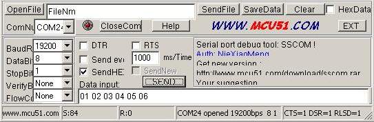
The data shown on individual display modules remains valid until it is overwritten with new data or until the display module is reset. If the display receives invalid data, it ignores it.
Mechanical Design
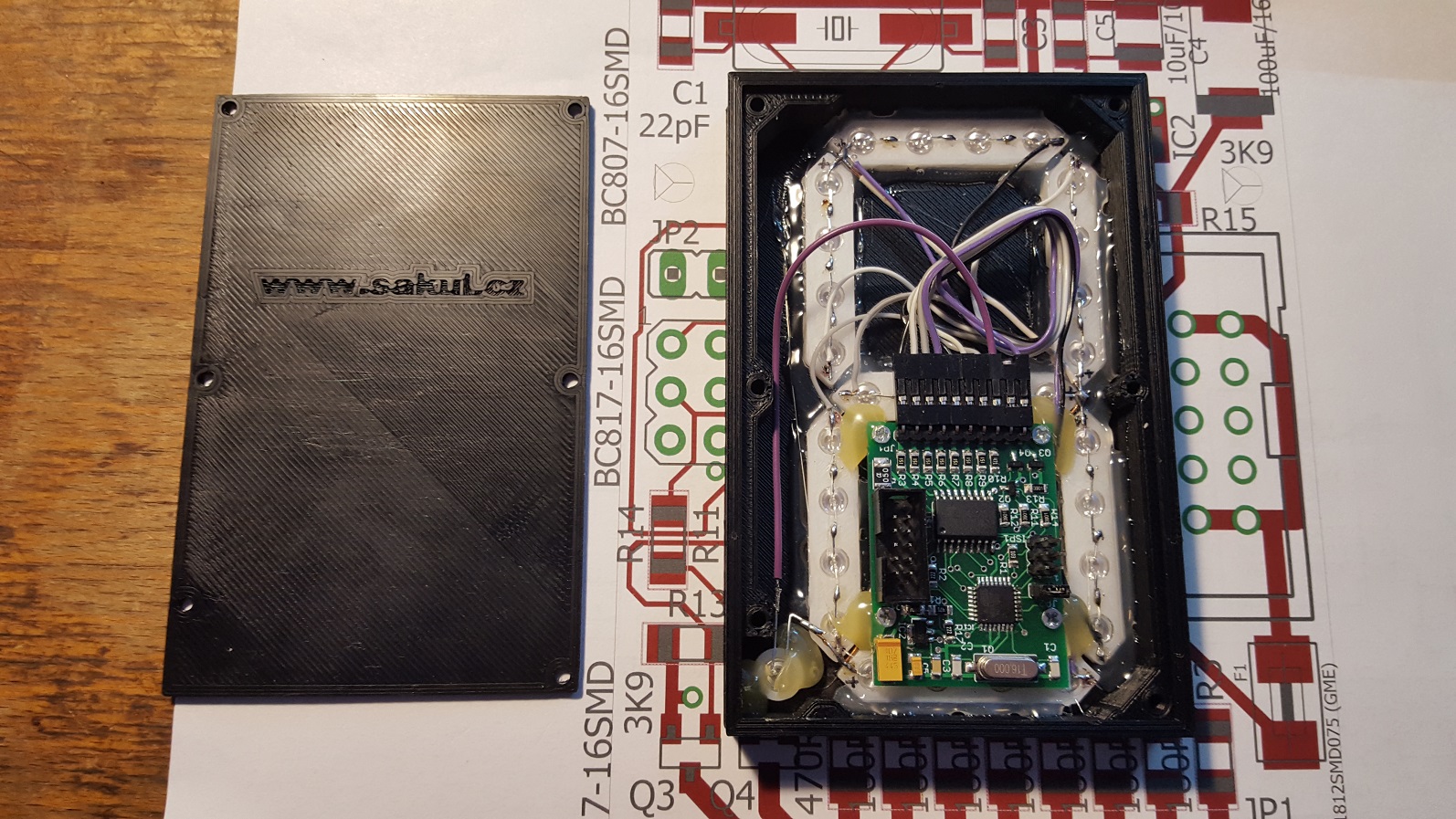
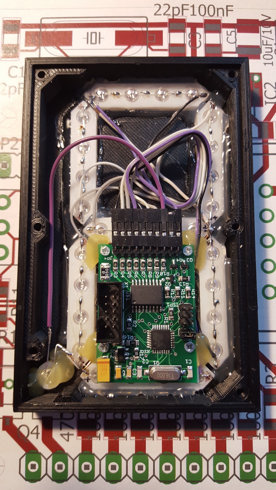
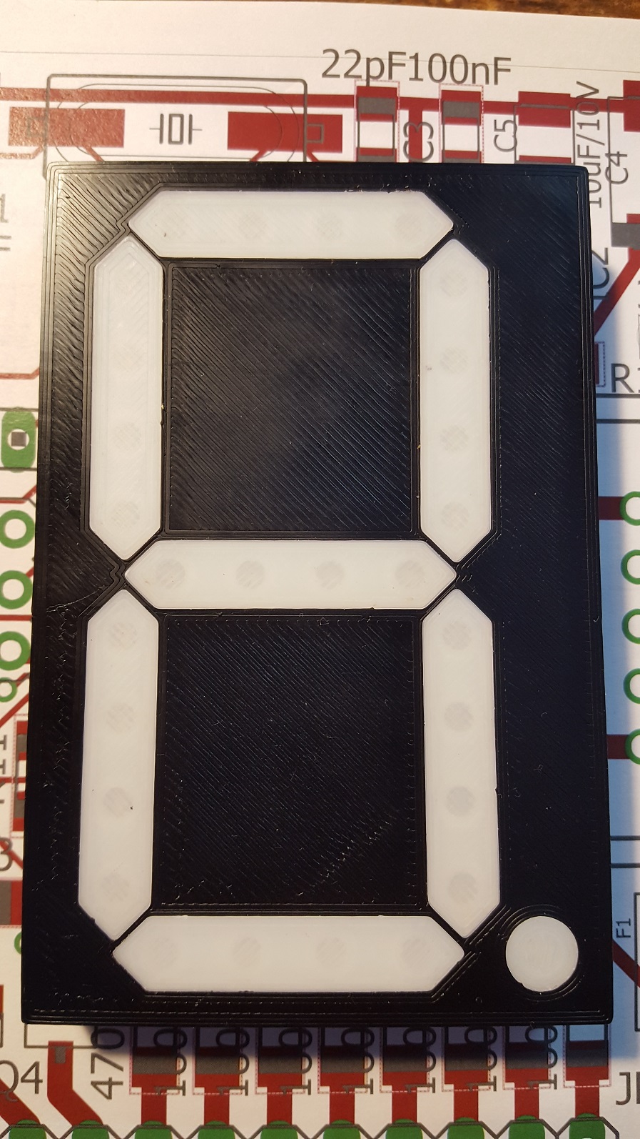
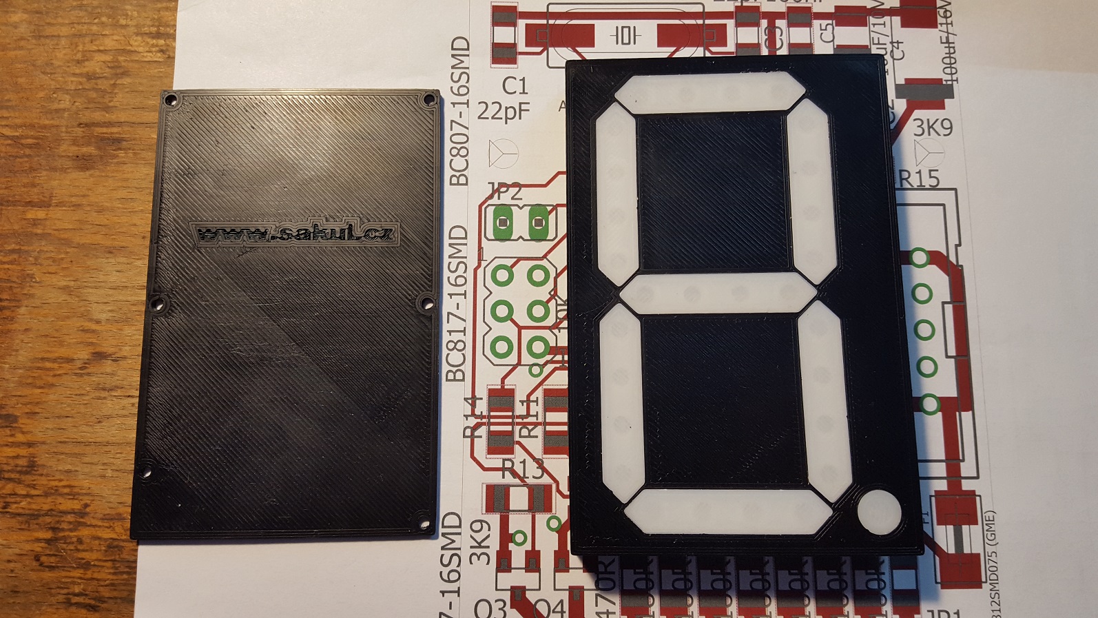
For this construction I also created an enclosure shaped as a seven-segment display. The enclosure can be printed on a 3D printer. The individual segments are printed from white plastic, while the enclosure and cover are printed from black plastic. LEDs are pressed into each segment and connected in series, which is clearly visible in the photos. The segments are then inserted into the enclosure and glued, for example with hot glue. After that, the individual segment LEDs are connected to the electronics, and the PCB is screwed into the enclosure with M2 screws. The rear cover can also be screwed on with M3 screws or simply glued. This creates a complete display module that can be mounted into a larger display. All connectors are easily accessible from the back, so interconnecting modules with a flat cable is straightforward.
For smaller displays, ordinary LEDs can be used. For larger displays, LED strips or other suitable light sources are more practical, depending on the size of the segments.
Photo Gallery
Documentation
Finally, you can download the complete documentation for the build. It also contains the Eagle project.
Notice
This construction is original author work. It may not be copied to other websites or used commercially without the author's permission. Linking to this website and to this construction is allowed. For more information, contact me. I also do not accept any responsibility for the behaviour of the device or for any damage caused by its use. The device is intended for personal use only. This construction uses microcontroller firmware that is subject to copyright. The program is licensed free of charge for personal use. Any sale is not allowed without the author's consent.