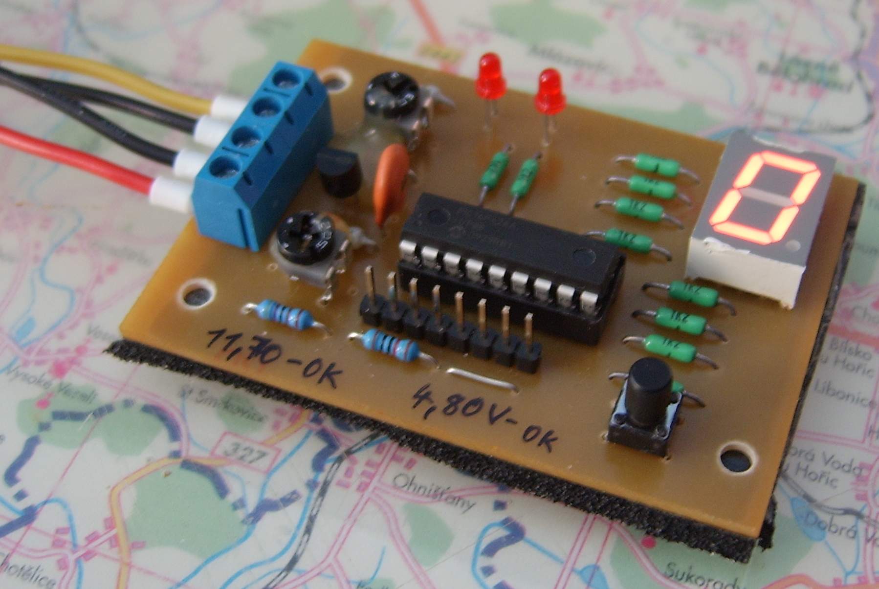
This simple device was designed to detect a common fault in ATX computer power supplies. It does not measure the output voltage itself, because that can be done with a normal multimeter. Its purpose is to detect output ripple, which is often caused by failing output capacitors.
In practice, a failing power supply is often behind an unstable computer. A normal multimeter may show all voltages within tolerance, yet the computer can suffer from random restarts, disk failures, system freezes and other unstable behavior. These problems can remain subtle for months before the supply fails completely. A simple tester that can reveal such a supply is therefore useful.
Main Parameters
| Supply | Directly from the tested power supply, using the +12 V rail. |
|---|---|
| Tested Rails | +5 V and +12 V. |
| Measurement Principle | Ripple detection. |
| Indication | Seven-segment display and LEDs. |
| Modes | Normal test mode and calibration mode selected by button. |
Schematic
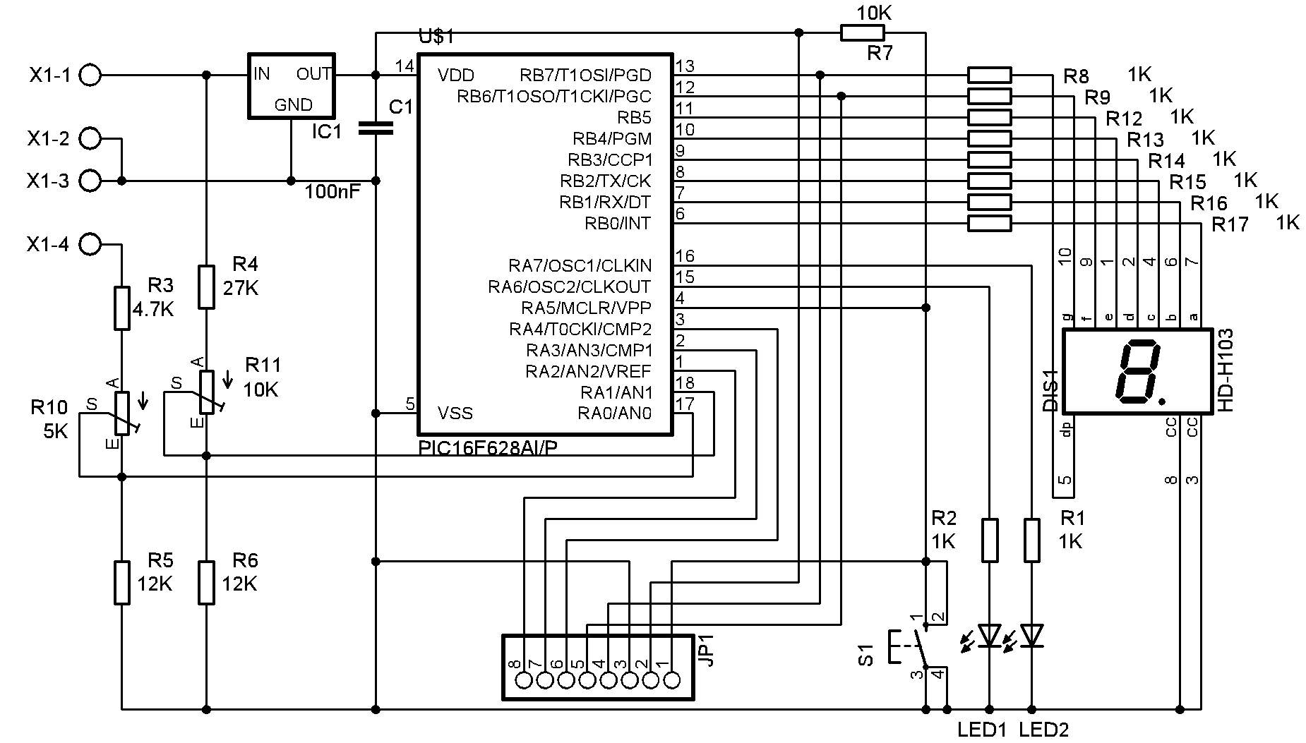
The circuit is simple thanks to the microcontroller. +12 V and +5 V from the tested power supply are connected to X1-1 and X1-4; X1-2 and X1-3 are GND. The tester is powered from the 12 V rail through a 7805 regulator.
The tested voltages are fed through voltage dividers to the microcontroller inputs and compared with an internal reference derived from the processor supply. A single seven-segment LED display connected to port B shows the number of detected dips. Two LEDs indicate which rail caused the fault: LED1 for 5 V and LED2 for 12 V.
Button S1 resets the display and LEDs with a short press. A long press of about three seconds switches the tester to calibration mode. JP1 is used for programming and also exposes unused microcontroller ports for possible future expansion.
PCB and Assembly Plan
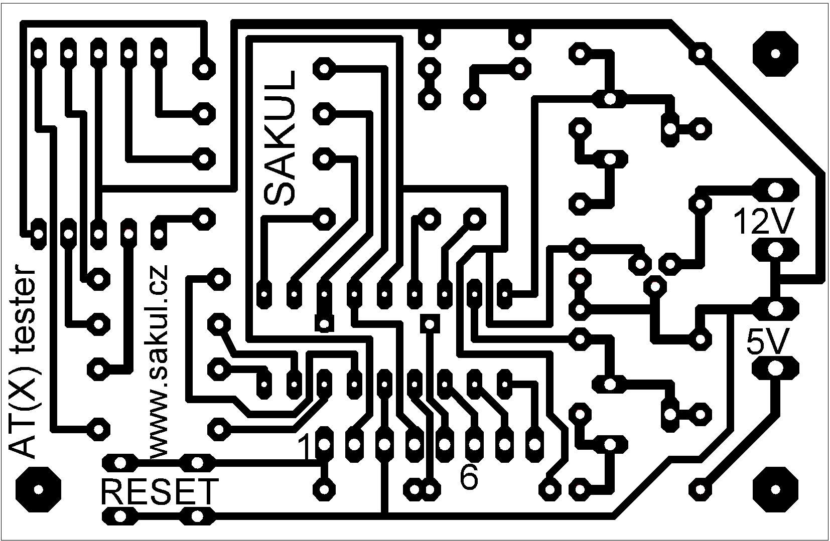
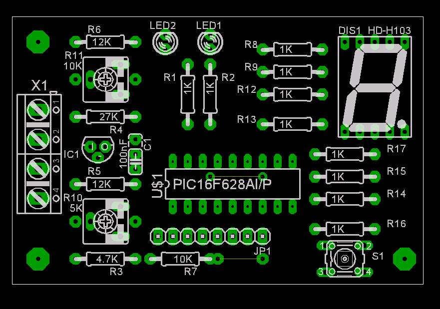
The PCB is a single-sided 45x69 mm board. Two wire jumpers must be fitted, one of them under the microcontroller. Fixed resistors may be fitted instead of trimmers if desired. During assembly, pay attention to traces routed between the microcontroller and display pins to avoid accidental bridges.
Fault Detection Principle
A normal multimeter cannot detect this kind of fault because it does not react fast enough to output ripple caused by bad filter capacitors. Such supplies can appear functional, but the output voltage may have spikes of several volts relative to the nominal value. An oscilloscope shows this clearly, but not everyone has one available.
The tester uses a PIC16F628A microcontroller with two internal comparators. The +5 V and +12 V rails are compared against an internal 3 V reference after the input dividers. If the comparator input is above 3 V, everything is normal. If it drops below 3 V and then rises above it again, the event is detected as a fault. A supply with excessive ripple produces many such events and is therefore easy to identify.
Operation
The tester has two modes: test and calibration. In test mode, the input voltages are compared with the reference. When a dip and return above the decision level is detected, the appropriate LED lights and the display shows 1. Further faults keep the LED lit and increment the display.
If the number of faults exceeds the display range, the decimal point lights and the display starts blinking. This blinking indicates a faulty supply. A good supply may occasionally show one to three events over several minutes, but a bad supply will make the display count continuously and usually starts blinking after only a few seconds.
The tester should be connected through a normal MOLEX connector to a free connector of the PC power supply. The supply should be tested inside the computer with all components connected. Testing without load can produce misleading results because the output voltages may not be stable and the supply may not start correctly.
The tester can also be connected while the PC is running, because the firmware starts measuring with a delay to avoid false detection during connection. Input evaluation is delayed in software and runs at 10 ms intervals. This makes the result readable and helps prevent false detections.
In calibration mode, entered by a long button press, trimmers R10 and R11 adjust the input voltage dividers. Calibration mode is indicated by a dash on the display and the LEDs are connected directly to the comparator outputs.
Calibration
After assembly, the tester must be calibrated using an adjustable 3-14 V supply. A two-channel laboratory supply is ideal. Set one channel to 5 V and the other to 12 V, connect the tester and enter calibration mode by holding S1.
For the 5 V rail, set the input voltage to 4.80-4.85 V and adjust R10 until LED1 just lights. When the voltage is increased to 4.90 V, LED1 should reliably turn off. Use the same approach on the 12 V rail with R11: set the detection threshold to 11.70-11.75 V, and LED2 should turn off at 11.80 V.
After calibration, it is useful to secure the trimmers, for example with hot glue, so they cannot drift mechanically. The exact threshold is not extremely critical because a faulty supply often has ripple peaks much larger than a few tenths of a volt.
Practical Experience
This is the second tester version I designed. The first one used discrete components, was more complicated and sometimes produced false detections. This microcontroller version is simpler to build, adjust and use.
The construction was tested with help from Comtex Network Systems, a computer service center with enough faulty samples for testing. That made it possible to tune the tester for good effectiveness.
The tester also found faults in supplies other than classic AT or ATX PC supplies. For other supply voltages, the input divider range has to be modified. The PCB allows fixed resistors to be fitted instead of trimmers. In calibration mode it is also possible to see whether the measured voltage is above or below the threshold.
This tester is not intended to compete with complex ATX power supply testers. It does not measure voltage; it only compares it. For this purpose, however, it is sufficient, inexpensive and firmware can still be improved through the programming connector without hardware changes.
Bill of Materials
| Designator | Qty | Value / Type | Note |
|---|---|---|---|
R1, R2 | 2 | 1K | |
R3 | 1 | 4.7K | |
R4 | 1 | 27K | |
R5, R6, R7 | 3 | 12K | |
R8-R17 | 10 | 1K | |
R10 | 1 | 5K | Alternative 4.7K. |
R11 | 1 | 10K | |
C1 | 1 | 100nF | |
LED1, LED2 | 2 | Red 3mm 2mA LED | |
DIS1 | 1 | HD-H103 | Common cathode. |
IC1 | 1 | 78L05 | |
US1 | 1 | PIC16F628A | Programmed microcontroller. |
S1 | 1 | PCB micro button | |
JP1 | 1 | 8-pin breakable jumper header | |
X1 | 1 | ARK500 2x2-pin PCB terminal block |
Documentation
The documentation package contains construction files, Eagle project and firmware for the microcontroller.
Configuration
| Configuration directive | __config _BODEN_OFF & _CP_OFF & _PWRTE_ON & _WDT_OFF & _LVP_OFF & _MCLRE_OFF & _INTRC_OSC_NOCLKOUT |
|---|
Declaration
This construction is original work and may not be republished on other websites or used commercially without my permission. Linking to this website and this construction is allowed. I assume no responsibility for the behavior of the device or for any damage caused by its use. The device is intended only for personal use.
This construction uses microcontroller firmware protected by copyright. A free license is granted for personal use. Any sale is not allowed without the author's permission. I collaborated with Botas on the firmware and it is published with his consent.