Published in Praktická elektronika 10/2016.
This is another custom-built circuit. This time it is a CO2 gas concentration meter. For maximum simplicity it uses a ready-made, calibrated detector module for this gas.
Technical Specifications
| Supply voltage | 8-12 V/DC or 6-10 V/AC |
|---|---|
| Current consumption | approx. 100 mA |
| CO2 indication | 10-LED bar graph plus 2 separate LEDs |
| CO2 indication range | 400-2200 ppm on the bar graph |
| LED thresholds | Red above 1500 ppm, yellow above 1000 ppm |
| External display | Backlit 2x16 character LCD over I2C |
| Communication | UART 9600 bps for diagnostics |
Construction Description
The CO2 meter uses a complete calibrated FIGARO CDM4161A module. This module has two analog outputs and one input. The main Vconc output provides the measured CO2 value as a voltage in the 400-4000 ppm range, corresponding to 0.4-4 V. Voltages outside this range are used to report additional states. For a detailed description, study the module datasheet. The second module output is CTRL. Among other things, it signals CO2 concentration above 1000 ppm and is deactivated when the value drops below 900 ppm. The last pin is RESET, which can be used to calibrate the CO2 sensor, for example after replacement. This input is not used in this construction, but the hardware is prepared so it could be controlled by a program change.
CDM4161A Pin Meaning
| Pin | Description |
|---|---|
1 | +5 V supply voltage |
2 | Vconc |
3 | CTRL |
4 | RESET |
5 | GND |
The construction evaluates all outputs of the CO2 module and visualizes them with a 10-step bar graph at 400, 600, 800, 1000, 1200, 1400, 1600, 1800, 2000 and 2200 ppm. Additional LED indications are used as well: the yellow LED lights when the value exceeds 1000 ppm and turns off only after dropping below 900 ppm. The red LED lights when the value exceeds 1500 ppm and turns off immediately after dropping below 1500 ppm. This red LED also lights during the whole sensor warm-up period, about 2 hours after power is connected.
Function Description
After voltage is applied through the power connector, the processor and CO2 module are initialized. Sensor warm-up is then started and takes 2 hours. This state is indicated by the red LED and flashing of the two middle LEDs on the bar graph. When the sensor is warmed up, the device enters normal operation, the red LED turns off and the current CO2 concentration is displayed on the bar graph. If no LED on the bar graph is lit, the concentration is below 400 ppm.
If a backlit 2x16 LCD is connected, it displays the exact concentration value or a message that the sensor is warming up. An external reader can also be connected through UART, but this option is not currently supported.
Schematic
The circuit is based on an ATMEGA328P-PU or ATMEGA8-PU processor, preferably mounted in a socket. The PCB also includes ISP1 programming connector, but if a single-sided board is used, not all required pins would be connected. Power is connected to US1, a standard PCB DC connector with a 2.1 mm center pin. Behind the connector is bridge rectifier B1, which protects the circuit against reverse polarity. AC supply voltage can also be used. Input voltage should not exceed 12 V for DC or 10 V for AC. If an external display is connected, voltage regulator IC2 7805 must be fitted with a heatsink or replaced with a switching regulator. Power presence is indicated by green LED1. Display is handled by bar graph LB10 connected to the processor through limiting resistors R3-R12, whose values can be in the 390R-1K range. Two separate LEDs, yellow LED2 and red LED3, are used for additional indication.
Connectors are also important: JP1 is the UART output, JP2 connects an LCD through I2C, JP3 connects the CO2 sensor module and JP4 currently has no function.
Printed Circuit Boards
The PCB size is 100 x 50 mm. The first layer is BOTTOM and the second layer is TOP.
Assembly Plan
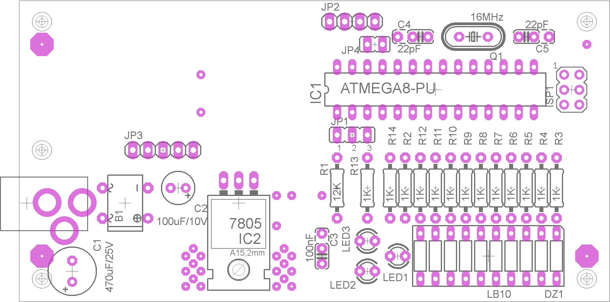
PCB and Assembly
The PCB is designed as double-sided, but it can be made as a single-sided board if two wire jumpers near IC2 and one below the FIGARO module are fitted. With the single-sided version, programming through ISP1 does not work because most of its traces are routed on the TOP layer. Capacitors C1 and C2 should be mounted lying down; the PCB is designed for this and they fit. IC2 is screwed to the PCB and copper areas on both BOTTOM and mainly TOP layers provide partial heat dissipation. A double-sided plated-through PCB is ideal.
CO2 Module Mounting
Before mounting, the original connector must be removed from the module. Only then is the module soldered lying down, as shown in the introductory image. Be careful when removing the original connector to avoid damaging the PCB. Hot air is recommended.
Documentation
The complete documentation package contains the build files, Eagle project and microcontroller firmware.
Notice
This construction is original author work. Copying it to other websites or using it commercially is not permitted without the author's consent. Linking to this website and this construction is allowed. The author accepts no liability for the behaviour of the device or any damage caused by its use. The device is intended only for personal use. The construction contains microcontroller firmware protected by copyright; any sale is not possible without the author's consent.