This stopwatch was designed as a custom project. Unlike previous stopwatch versions, the time is predefined and the device counts down. It includes output for an external large display and allows the user to edit 4 preset times. The construction uses an Arduino Pro Mini board, which simplifies and reduces the cost of the whole design. On the other hand, high timing precision should not be expected, but that is not a priority for this construction.
Technical Specifications
| Supply voltage | 8-12 V/DC |
|---|---|
| Current consumption | approx. 50-100 mA |
| Display output | RJ11 cable or 433 MHz wireless link |
| Internal display | Backlit 2x16 LCD over I2C |
| External display | Optional 4 digits, 150/200 mm |
| Number of presets | 5, of which 4 are user-editable |
| Time range | 99:59, minutes:seconds |
| Control | Internal buttons, external optically isolated RJ9 inputs |
Control
After power is connected, the internal LCD lights up and the stopwatch initializes. During this time the LCD shows information about the author, stopwatch version and firmware, and optionally owner information. After initialization the stopwatch enters normal operation. The first LCD line shows the selected preset and the second line shows the countdown. Buttons or UP/DOWN inputs cycle through the presets. The selected preset is copied to the countdown line. START begins the countdown. During countdown all buttons and inputs are blocked except RESET. When the countdown finishes, the time stops at 00:00. The countdown can then be started again with START or the preset can be changed with UP/DOWN.
If the preset times are not suitable, they can be edited by the user. To enter setup mode, hold START at any time and briefly press RESET. When initialization starts, release START. After initialization the stopwatch enters setup mode and the LCD shows 4 current times. The cursor flashes on the minutes position of the first time, indicating the editable field. UP/DOWN changes the value. Minutes can be set from 00 to 99 and seconds from 00 to 59. START moves to the next editable position. After all positions are passed, the times are saved and the stopwatch returns to setup mode. Press RESET at any time to leave setup mode and return to normal operation. Only the first 4 times can be edited; the fifth is fixed.
External Display
When an external display is connected by cable or wirelessly, it shows the running countdown, i.e. the value from the lower LCD line. With a cable connection the recommended maximum cable length is 10-15 m. Longer cables are not guaranteed to work reliably. With wireless transmission the maximum distance is 10 m for Bluetooth HC-05/06 modules. With 433 MHz modules, range is about 10-200 m depending on antenna and HC-11/12 configuration.
The external panel supply voltage is 12 V / 1.5 A DC. The center pin of the power socket is positive and the outer contact is negative. For cable connection between display and stopwatch, a jumper on the rear side of the display must be changed according to the display instruction video.
HC-12 Configuration
| Communication channel | 1 |
|---|---|
| Baud rate | 19.2 Kb/s |
| RF power | -1 dBm |
| Operating mode | FU3 |
Default Times
| Preset | Value |
|---|---|
Time 1 | 08:00 |
Time 2 | 12:00 |
Time 3 | 15:00 |
Time 4 | 18:00 |
Time 5 | 20:00 |
The times are stored in stopwatch memory and are retained even after power loss. The currently selected preset is stored as well.
Schematic
The core of the construction is an Arduino Pro Mini board, which includes the processor and additional circuits such as the voltage regulator. It is inserted into a socket on the base board, which contains support circuits such as the MAX232 converter, control buttons and optically isolated inputs using PC817 optocouplers for remote control.
Printed Circuit Board
The PCB size is 100 x 61 mm. The first layer is BOTTOM and the second layer is TOP.
Assembly Plan
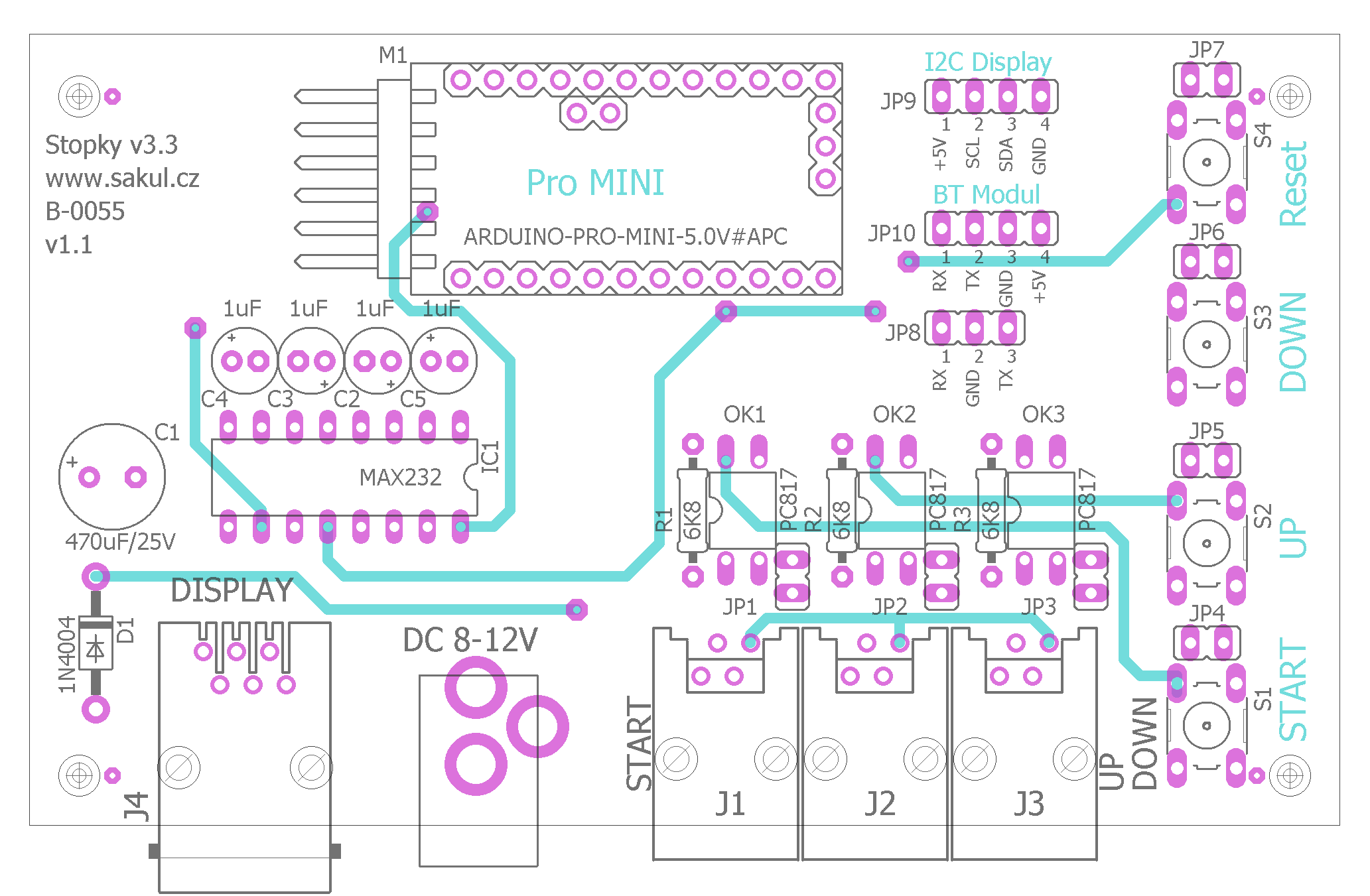
During assembly, make sure all vias are soldered through; otherwise there should be no special issues.
PCB and Assembly
The PCB is double-sided and contains several vias. Most of them are located on components that can be soldered from both sides, such as resistors, but some must be made with thin wire inserted through the hole and soldered from both sides.
LCD Display
The stopwatch uses a 2-line, 16-character LCD. To simplify wiring as much as possible, the display is connected through JP9, which carries the I2C bus. The display must therefore use a suitable adapter. This construction uses the GY-IICLCD adapter.
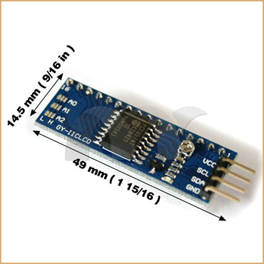
The adapter board and the stopwatch schematic both clearly label the pins. The adapter also has a small trimmer for contrast adjustment. If nothing appears on the display after connection, try adjusting the contrast.
| Pin | Meaning |
|---|---|
JP9-1 | +5 V |
JP9-2 | SCL |
JP9-3 | SDA |
JP9-4 | GND |
Uploading Firmware
Because the stopwatch uses an Arduino Pro Mini board, firmware can be uploaded using a suitable USB/TTL converter. A suitable converter has +5 V, GND, TX, RX and DTR pins, for example CP2104. The converter-to-board connection is shown below.
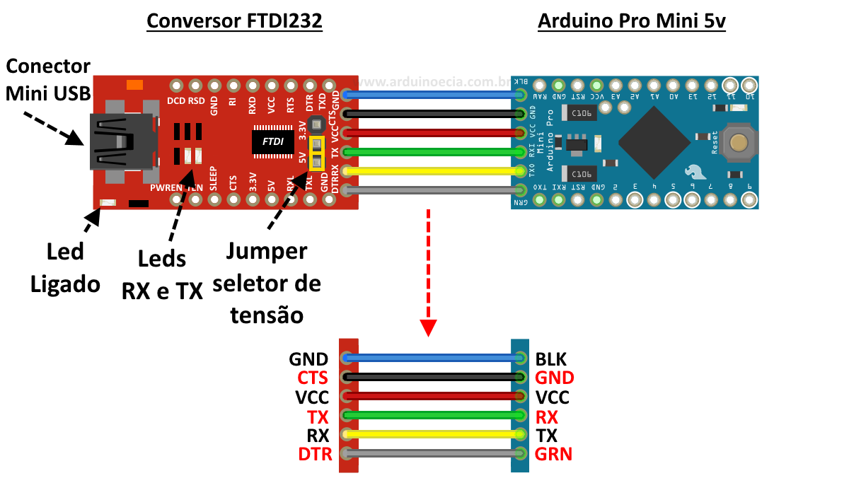
The wiring is simple. If using a different USB/TTL converter than shown, make sure RX and TX are crossed between the converter and processor board. The image shows all pins connected, but this is not strictly necessary. The important pins are RX, TX, DTR and GND; if the converter powers the stopwatch during programming, also connect VCC +5 V. Firmware is uploaded with XLoader by selecting DEVICE Stopky v3.3 (ATmega328), choosing the COM port and selecting the required HEX file. Press UPLOAD to flash the firmware.
Arduino Pro Mini Board
This construction uses an Arduino Pro Mini board, which greatly simplifies and lowers the cost of the design. The disadvantage is reduced timing precision due to the low-quality resonator used for processor clocking. Pay attention to the exact board variant; only the original-compatible layout is suitable for this construction.
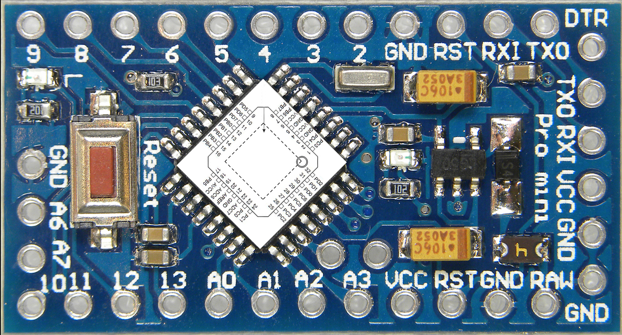
The important detail is the two pins above A2 and A3. Some clones place these pins elsewhere or do not expose them at all.
Bill of Materials
| Designator | Value / type |
|---|---|
R1-R3 | 6K8 |
C1 | 470uF/25V |
C2-C5 | 1uF/25V |
D1 | 1N4004 |
OK1-OK3 | PC817 |
IC1 | MAX232N |
M1 | Arduino Pro Mini |
JP1-JP7 | 2-pin jumper header |
JP8 | 3-pin jumper header |
JP9 | 4-pin female header |
JP10 | 4-pin female header |
J1-J3 | RJ connector WEBP 4-4 LP (GME) |
J4 | RJ connector WEBP 6-6 (GME) |
S1-S4 | TC-0106-T (GME) |
US1 | PC-GK2.1 (GME) |
Documentation
The complete documentation package contains the build files, Eagle project and microcontroller firmware.
Notice
This construction is original author work. Copying it to other websites or using it commercially is not permitted without the author's consent. Linking to this website and this construction is allowed. The author accepts no liability for the behaviour of the device or any damage caused by its use. The device is intended only for personal use. The construction contains microcontroller firmware protected by copyright; any sale is not possible without the author's consent.