Published in Praktická elektronika 1/2017.
This device was made on request for monitoring battery charging. The original assignment was only to indicate an approximate current value using several LEDs. Another requirement was to use an integrated current sensor capable of measuring both positive and negative current. During the design I decided to add voltage measurement and display the values on an LCD. With these values available, power calculation was added and a simple wattmeter was created.
Technical Specifications
| Supply voltage | 8-25 V/DC, or 8-15 V depending on the selected supply variant. |
|---|---|
| Current consumption | approx. 30 mA |
| Current measurement range | +/- 20 A |
| Voltage measurement range | 0-30 V/DC, or 0-15 V depending on the selected variant. |
| Current indication | 8 LEDs as a bar graph. |
| Optional display | Backlit 4x20 character LCD on I2C bus. |
| Communication output | UART 9600 bps |
Circuit
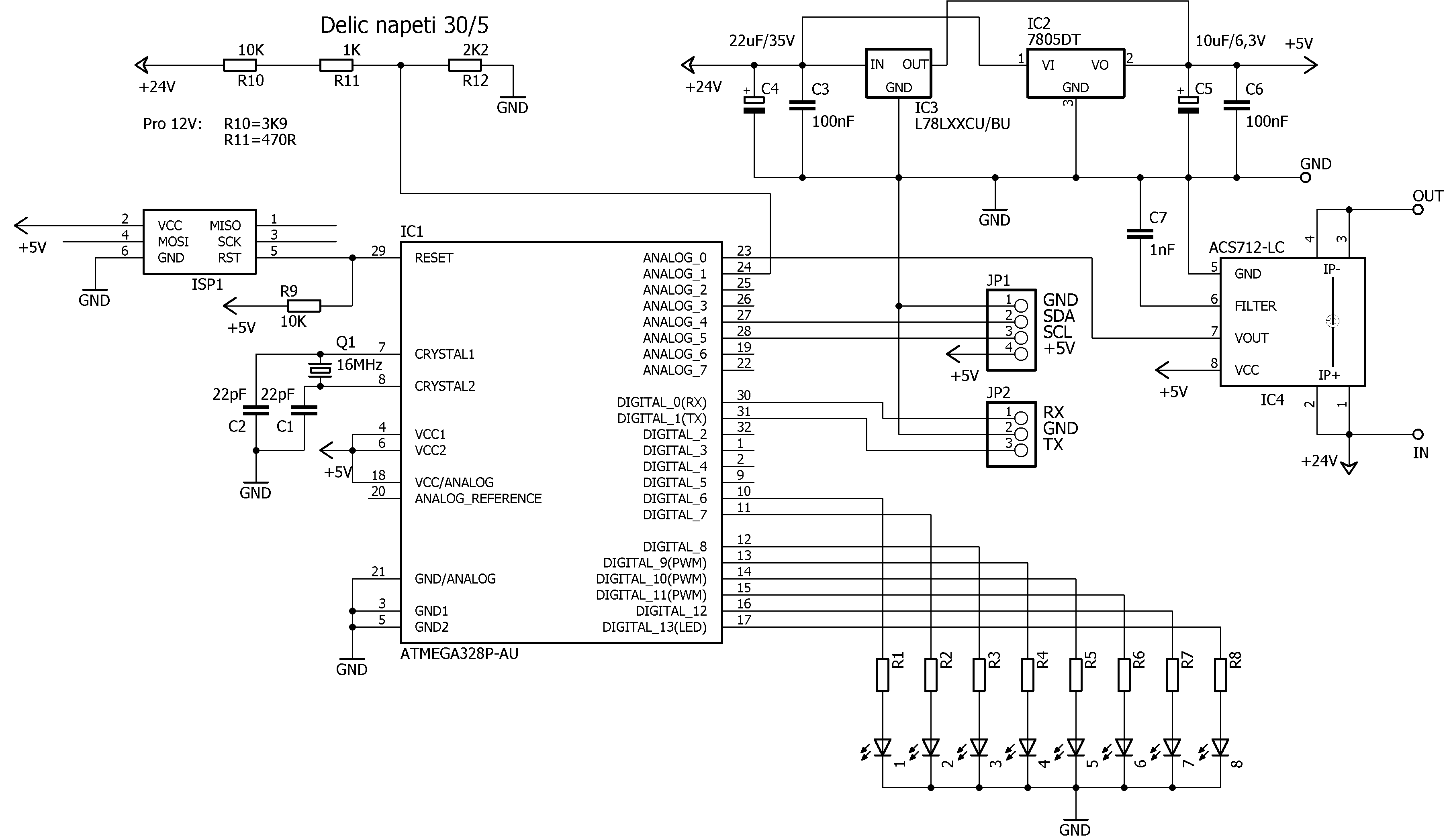
The circuit is fairly simple thanks to the ATMEGA328P-AU microcontroller. Supply voltage conditioning is handled by IC2 or IC3, depending on which one is used; only one of them must be fitted. Filtering capacitors are C3-C6. Current measurement uses an ACS712 integrated current sensor with a +/- 20 A range. This sensor requires only capacitor C7, 1 nF. Its output is an analog voltage in the 0-5 V range. With zero current through the sensor the output is exactly 2.5 V. Positive current increases this voltage and negative current decreases it. The sensor resolution is 100 mV / 1 A.
Current flow is indicated by 8 LEDs. The schematic then contains only a few connectors: JP1 for the display, JP2 for UART output and ISP1 as a service connector. Voltage measurement is handled by a divider made from resistors R10-R12.
Schematic
Printed Circuit Boards
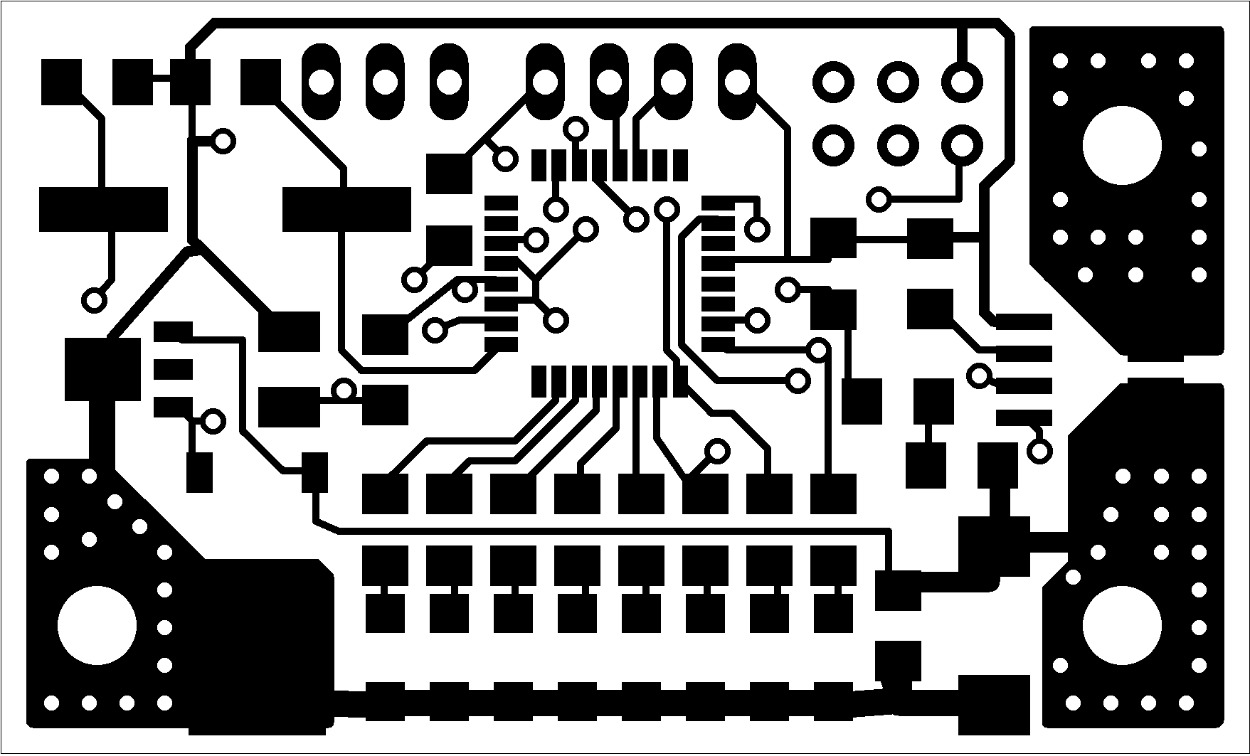
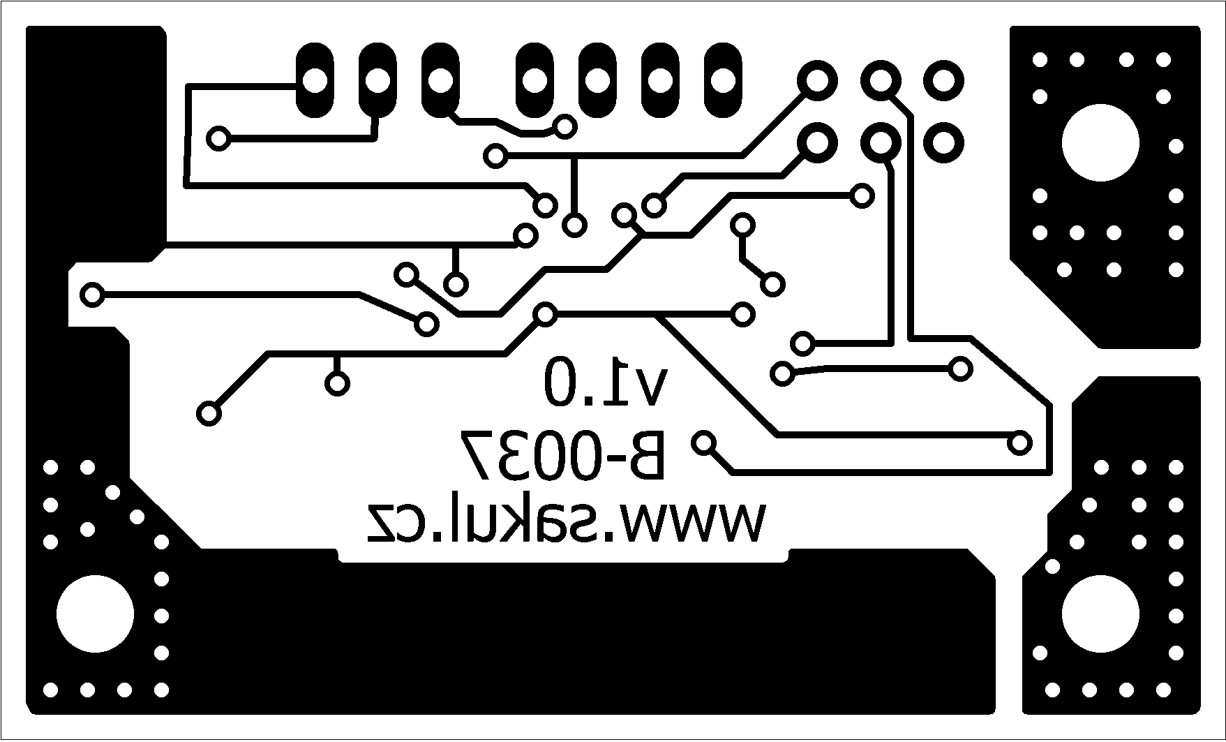
The PCB size is 50 x 30 mm. The first layer is TOP and the second layer is BOTTOM.
Assembly Plan
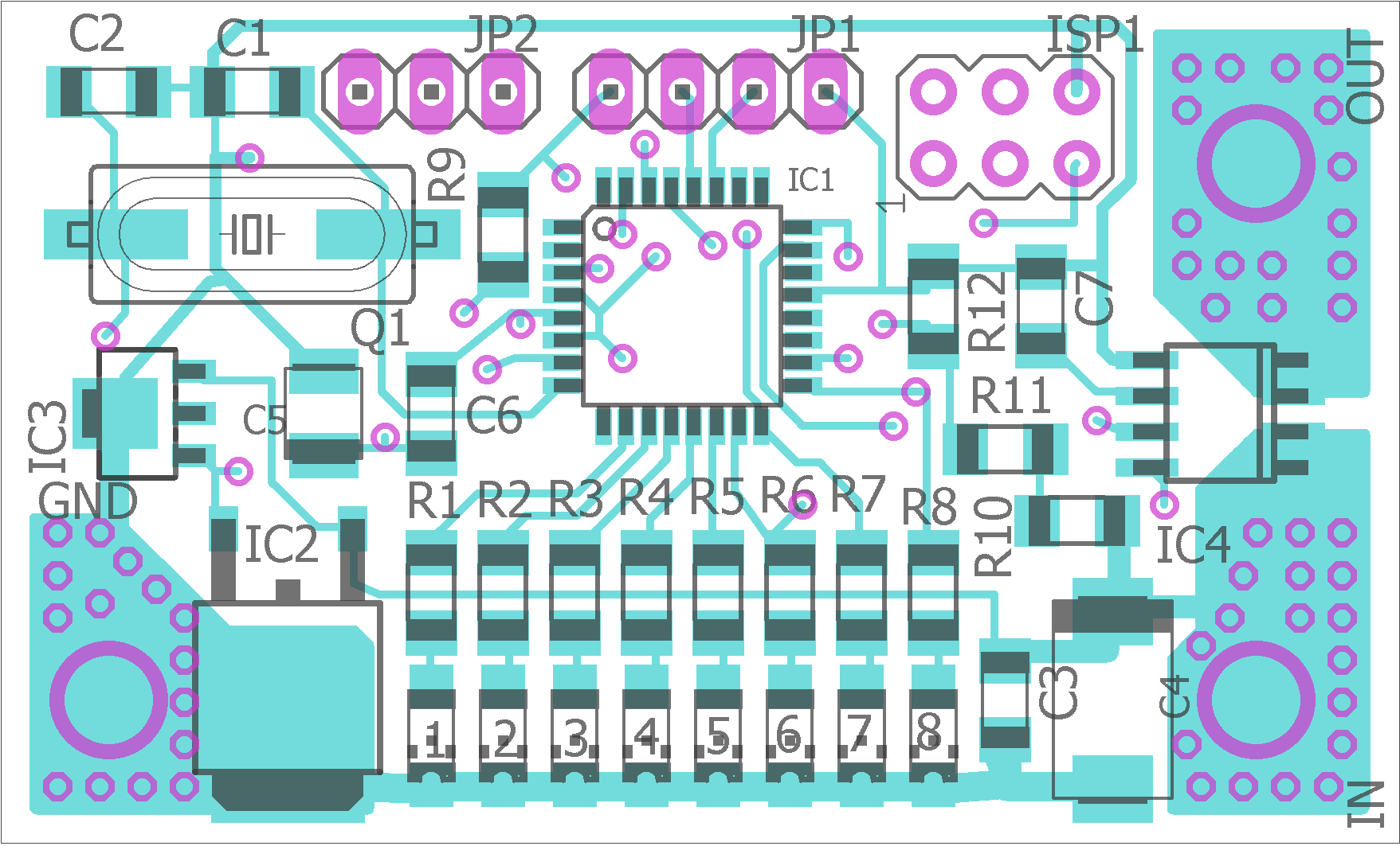
PCB and Assembly
As visible in the images, all components except connectors JP1, JP2 and ISP1 are SMD. Careful assembly is therefore necessary. The PCB also contains several vias, so if the board is not plated through, they must be made using thin wire soldered from both sides. It is recommended to start with the processor and then continue from the smallest components to the largest ones.
Function Description
The primary function of this device is current measurement. The current is indicated using a column of LEDs as a bar graph. If current flows from IN to OUT, it is considered positive and is displayed with the following thresholds:
| LED | Value | Color |
|---|---|---|
LED1 | 100 mA | Green |
LED2 | 500 mA | Green |
LED3 | 1 A | Yellow |
LED4 | 2 A | Yellow |
LED5 | 3 A | Yellow |
LED6 | 4 A | Red |
LED7 | 5 A | Red |
LED8 | 6 A | Red |
If current flows from OUT to IN, it is negative current and is indicated by flashing the whole LED column. The actual current value is not shown on the LEDs. A 4-line, 20-character LCD can be connected through the I2C bus on JP1 to display more accurate measured values, including negative current, voltage on the IN terminal and calculated power. A consumption value may be available in the future. UART output is also available on JP2 for debugging.
Connectors
| Connector | Description |
|---|---|
JP1 | External 4x20 character LCD connection. |
JP1.1 | GND |
JP1.2 | SDA |
JP1.3 | SCL |
JP1.4 | +5 V, max. 50 mA |
JP2 | UART 9600 bps TTL communication. |
JP2.1 | RX |
JP2.2 | GND |
JP2.3 | TX |
ISP1 | Service connector. |
IN | Positive voltage input 8-25 V/DC, or 8-15 V. |
OUT | Positive voltage output. |
GND | Negative voltage, ground. |
Final Notes
Be very careful when connecting the device, because reversed polarity will immediately destroy it.
Documentation - updated 25.08.2016
The complete documentation package contains the build files, Eagle project and microcontroller firmware.
25.08.2016 - Firmware v1.3 was added with AT command support and power measurement. See the updated documentation.
Notice
This construction is original author work. Copying it to other websites or using it commercially is not permitted without the author's consent. Linking to this website and this construction is allowed. The author accepts no liability for the behaviour of the device or any damage caused by its use. The device is intended only for personal use. The construction contains microcontroller firmware protected by copyright; any sale is not possible without the author's consent.