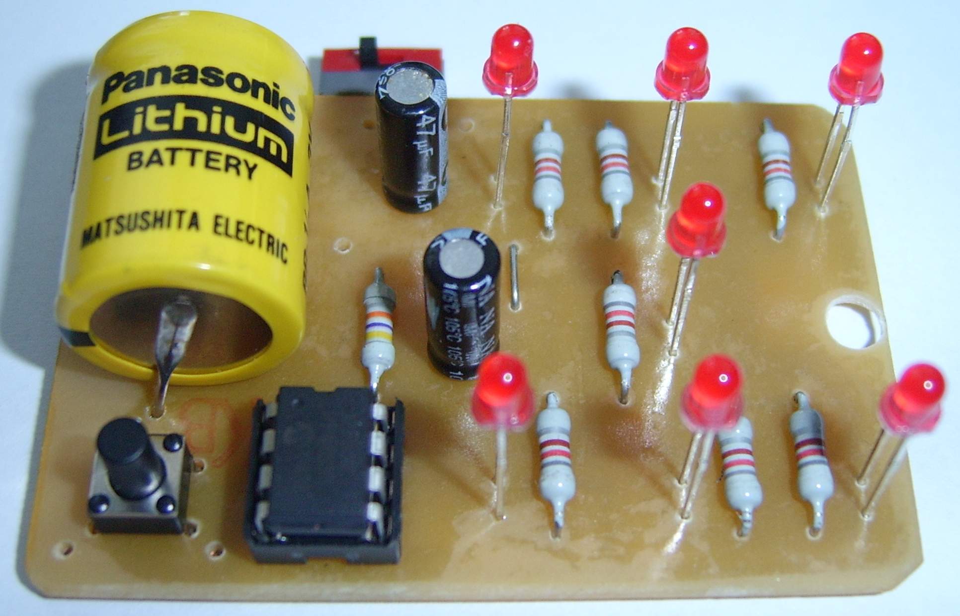
Although there are many electronic dice projects available, this construction was designed as a simple custom version. The displayed number from 1 to 6 uses the same layout as a classic dice. The main goal was a very simple circuit, which is easy to achieve with the PIC12F508 microcontroller.
The device also has very low current consumption when low-current 2mA LEDs are used, so it can be powered from a small 3V lithium battery. The whole construction can be fitted into a suitable plastic instrument case, for example KM27. Thanks to its simplicity, it is suitable even for complete beginners.
Main Parameters
| Controller | PIC12F508. |
|---|---|
| Display | LED display of numbers 1 to 6 in the same layout as a classic dice. |
| Supply | 3-5 V, the prototype used a 3 V lithium battery. |
| PCB | Single-sided board, 42x62 mm. |
| Enclosure | A suitable plastic instrument case, for example KM27. |
Schematic
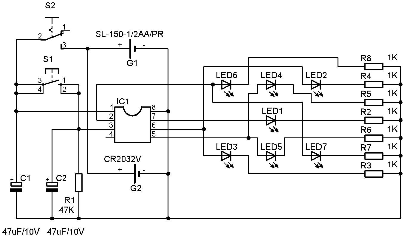
The schematic shows that the whole device is very simple. The heart of the circuit is a PIC12F508 microcontroller, so only a minimum number of additional parts is required.
How It Works
The device is switched on with S2. LED1 starts blinking to indicate that the dice is ready. Pressing S1 starts the random draw. All LEDs light up and after roughly 3 seconds the result is displayed.
The duration of the draw can be influenced by capacitor C2. A higher value means a longer draw time. In firmware version 1.0, the result stays displayed until S1 is pressed again.
To save battery power, firmware version 1.1 changes this behavior: the result is displayed for about 30 seconds, then all LEDs turn off and LED1 starts blinking again.
| Firmware Version | Behavior After Draw |
|---|---|
1.0 | The result remains displayed until S1 is pressed again. |
1.1 | The result is displayed for about 30 seconds, then the LEDs turn off and LED1 starts blinking again. |
PCB and Assembly Plan
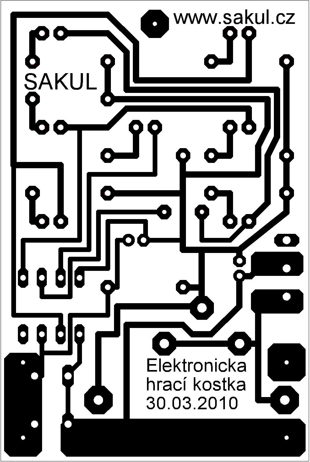
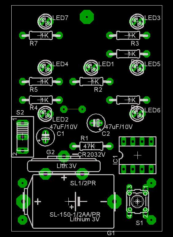
The PCB is a single-sided board sized 42x62mm. Assembly should be straightforward; do not forget to fit the wire jumper.
Bring-Up and Settings
The device is powered from 3-5V. The prototype used a 3V lithium battery. There is nothing to adjust; with careful assembly the dice works on the first power-up. The electronics can be installed into a KM27 case or a similar enclosure.
Microcontroller Configuration
| Item | Setting |
|---|---|
Oscillator | Internal. |
Watchdog | OFF. |
MCLRE | OFF. |
Code protection | As preferred. |
Documentation
The documentation package contains the construction files, Eagle project, microcontroller firmware and related materials.
Declaration
This construction is original work and may not be republished on other websites or used commercially without the author's permission. Linking to this website and this construction is allowed. The author assumes no responsibility for the behavior of the device or for any damage caused by its use. The device is intended only for personal use.
This construction uses microcontroller firmware protected by copyright. A free license is granted for personal use. Any sale is not allowed without the author's permission.