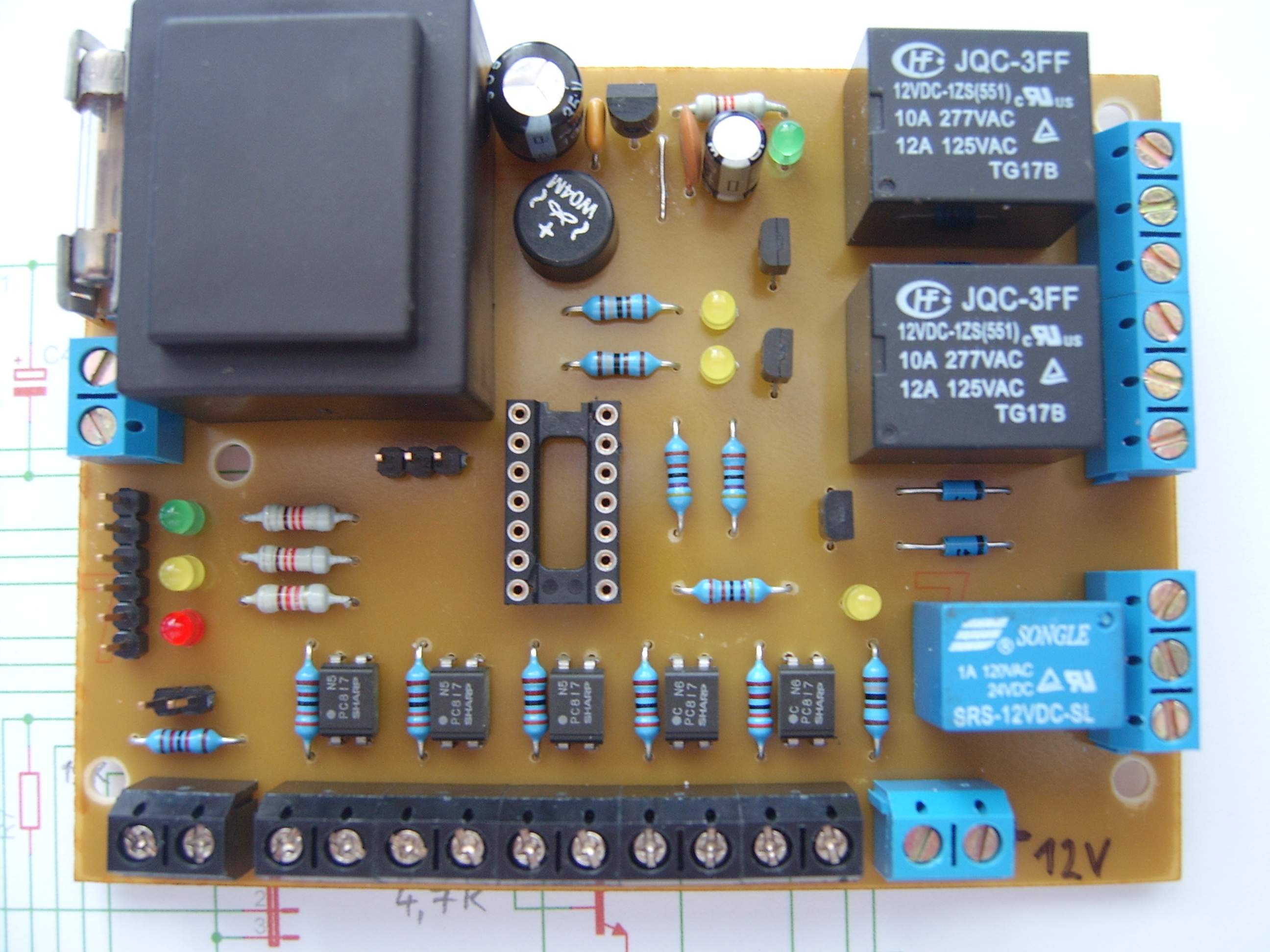
This project is a microcontroller-based controller for an electrically operated gate. It provides manual and automatic modes, input monitoring, optical safety beam handling, relay outputs for the drive and signalling, and fault indication. The original construction was published in Praktická elektronika 4/2011.
Technical Parameters
| Power supply | 230 V AC. |
|---|---|
| Remote receiver supply | 12 V DC, unregulated. |
| Fuse | F0.1 A glass fuse. |
| Inputs | Optically isolated. |
| Outputs | Relay outputs. |
| Controller | PIC16F630 or PIC16F676. |
| PCB | Single-sided 100 x 75 mm PCB with one wire jumper. |
Inputs and Outputs
| Signal | Port | Type | Description | Active state |
|---|---|---|---|---|
S1 | RA0 | Input | Gate closed sensor. | LOG 0 |
S2 | RA1 | Input | Gate open sensor. | LOG 0 |
S3 | RA2 | Input | Motor rotation / gate movement sensor. | LOG 0 |
OPTZ | RA4 | Input | Optical safety beam. | LOG 0 |
TLAC | RA5 | Input | Control button and remote-control input. | LOG 0 |
VIP | RA3 | Input | Manual / automatic mode switch. | Automatic in LOG 0 |
RE1 | RC0 | Output | Gate closing relay. | LOG 1 |
RE2 | RC1 | Output | Gate opening relay. | LOG 1 |
RE3 | RC2 | Output | Gate-in-motion signalling relay. | LOG 1 |
Operation
In automatic mode the controller checks the current gate position. If the gate is open or in an undefined position and the optical safety beam is clear, it automatically closes after about 30 seconds. If the beam is interrupted, the controller waits for it to clear; a longer interruption is reported as a minor fault and must be acknowledged. During movement, the controller monitors the motor movement sensor, the safety beam and the relevant end-position sensor.
In manual mode the controller ignores the optical beam and automatic timers. The gate is controlled only by the button or remote control. If the position is undefined, the first command opens the gate for safety reasons. Movement reversal is allowed only after reaching an end position.
Fault Indication
| Red LED on | Minor fault, such as interrupted optical beam or missing pulses from the movement sensor S3. |
|---|---|
| Red LED flashing | Serious fault, such as S1 and S2 active at the same time or the control button held during power-up. |
Hardware
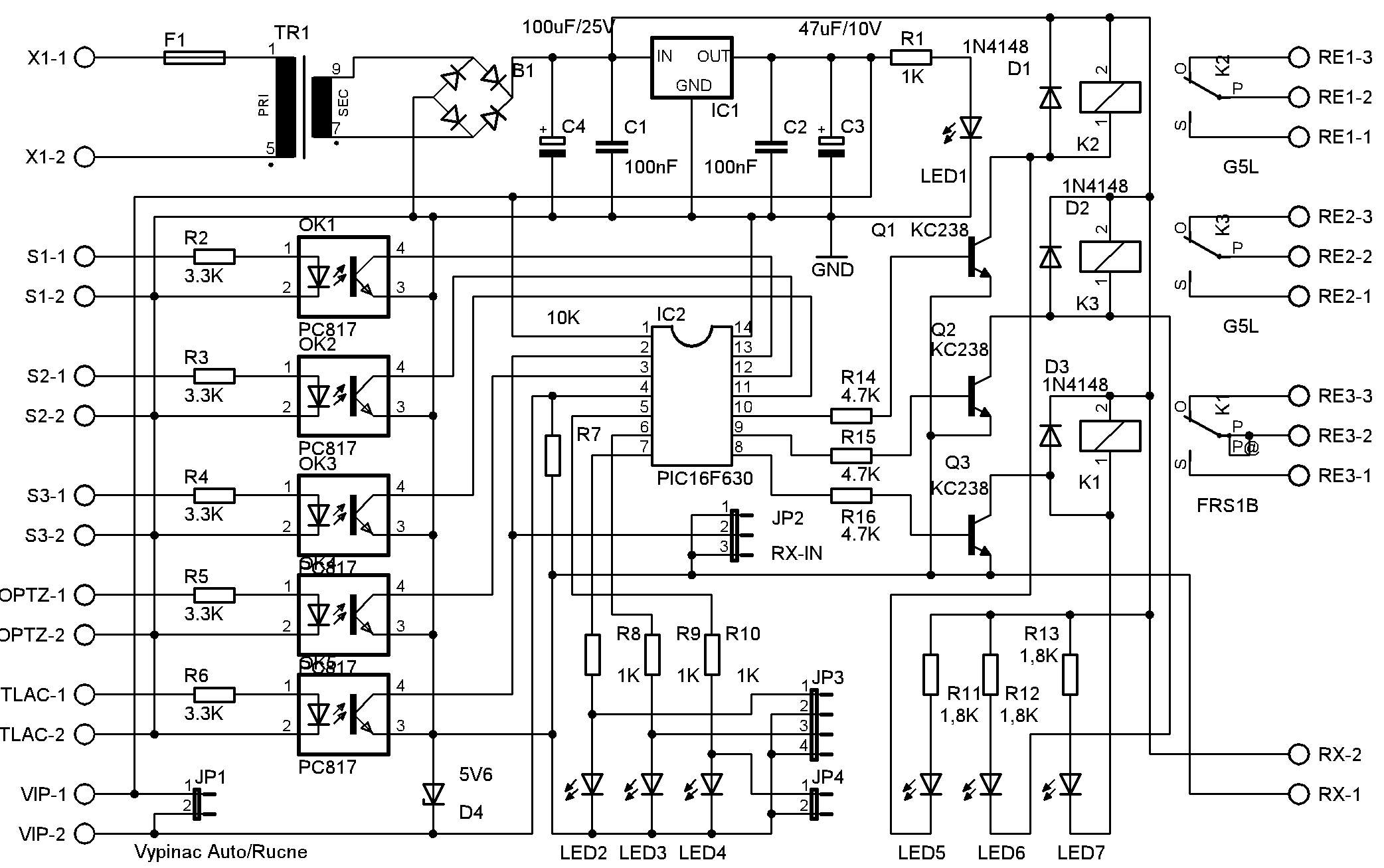
The controller is built on a single-sided PCB and is powered directly from 230 V AC. The logic supply for the PIC16F630/PIC16F676 is derived through a transformer, bridge rectifier and 78L05 regulator. Relay outputs RE1 and RE2 drive the open/close directions and should be used to drive suitable contactors for the actual motor. RE3 is intended for a beacon or other optical signalling.
Schematic
PCB and Assembly
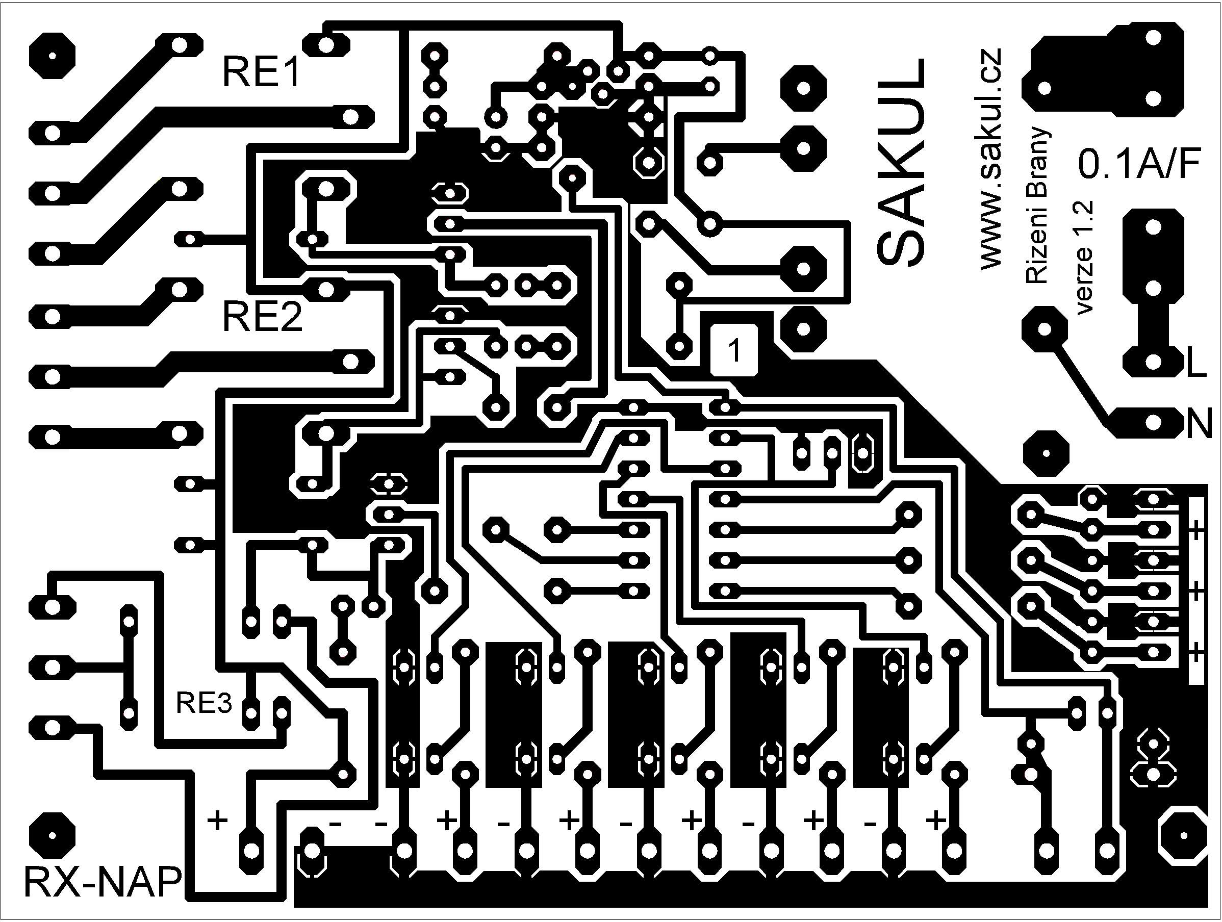
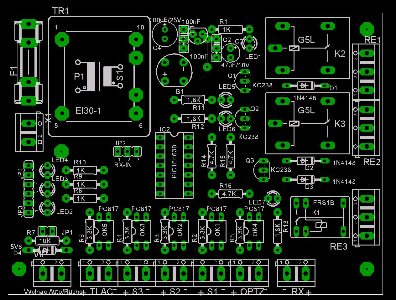
The PCB is a 100 x 75 mm single-sided board. With careful assembly the device should work on the first power-up and does not require adjustment. Do not forget the wire jumper.
Processor Configuration
| Item | Setting |
|---|---|
Oscillator | Internal oscillator. |
Watchdog | OFF. |
MCLRE | OFF. |
Code protection | As required. |
Documentation
The documentation package contains construction files, Eagle project files and firmware for the processor. An additional ZIP archive contains the VIP modification that allows closing the gate in automatic mode using the button.
Disclaimer
This is an author project intended for personal use. The author does not accept responsibility for device behaviour or any damage caused by its use. The microcontroller program is copyrighted and may be used free of charge for personal use only.