This construction is an electronic controller for a live trap. Older versions used mechanical triggering, then resistive sensing and motorized triggering, but the resistive sensors gradually became dirty and had to be cleaned. Optical detection was considered, but rejected because the trap is battery powered and must run for months.
The breakthrough was PIR detection. A PIR sensor has consumption in the hundreds of microamps, is contactless and can be placed outside the trap. This system worked for years with very high efficiency. Later, the mechanical microswitch used to indicate activation and disconnect the battery became problematic, so this new controller removes that mechanical element as well.
The controller is based on a small microcontroller. A later version was planned with wireless reporting, battery voltage monitoring, servo actuation, SMD construction, 4.5 V supply and consumption below 100 uA.
Main Parameters
| Supply | 7-15 V. |
|---|---|
| Current Consumption | Approximately 3 mA. |
| Detection | PIR sensor module. |
| Trigger Actuation | Motor-driven linkage. |
| Activation Mode | PIR module or push button. |
Schematic
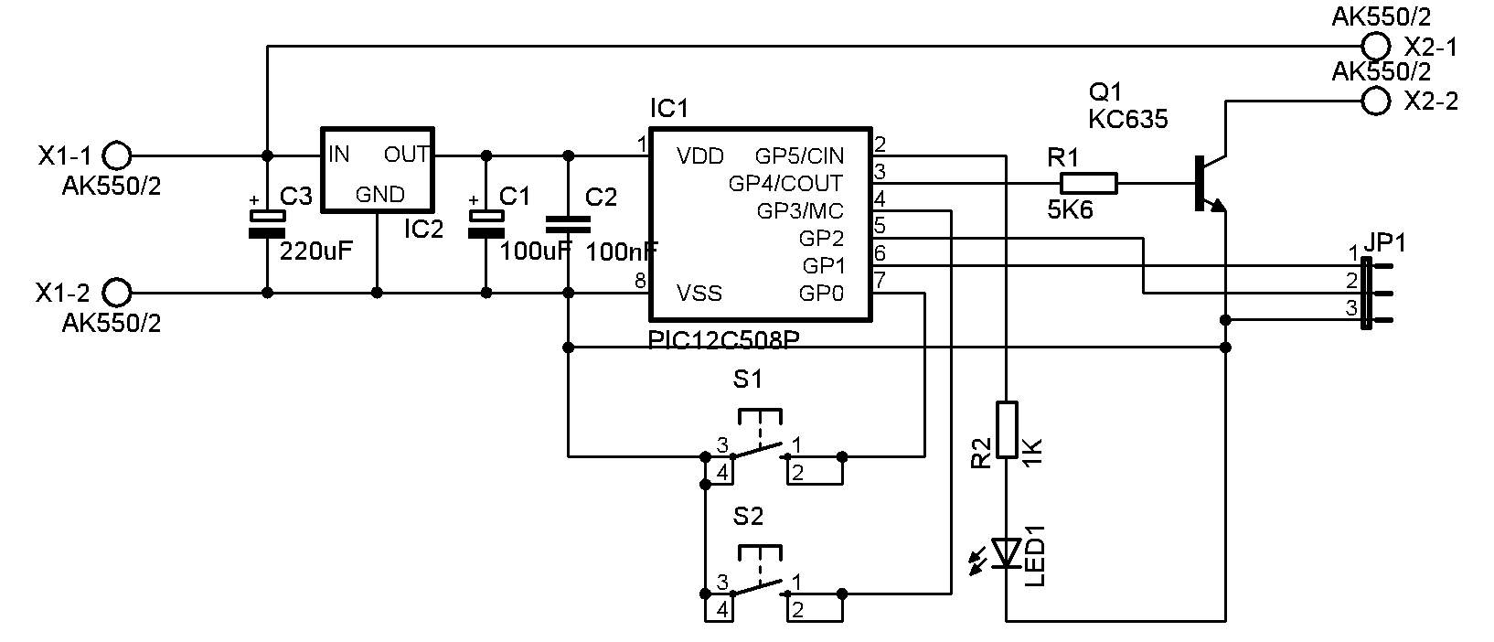
The electronics are very simple thanks to the PIC12F508 microcontroller. Supply voltage is connected to X1 and regulated to 5 V for the processor and PIR module. X2 connects the motor that releases the trap mechanism. The motor is switched by NPN transistor Q1, originally KC635; a type rated for about 1 A is suitable.
S1 is a test button that simulates PIR activation and triggers the mechanism. S2 resets the processor and puts the trap back into active mode. JP1 connects the PIR module: pin 1 is the active output from the PIR module, pin 2 is positive supply and pin 3 is GND. LED1 indicates the current state of the controller.
PCB and Assembly Plan
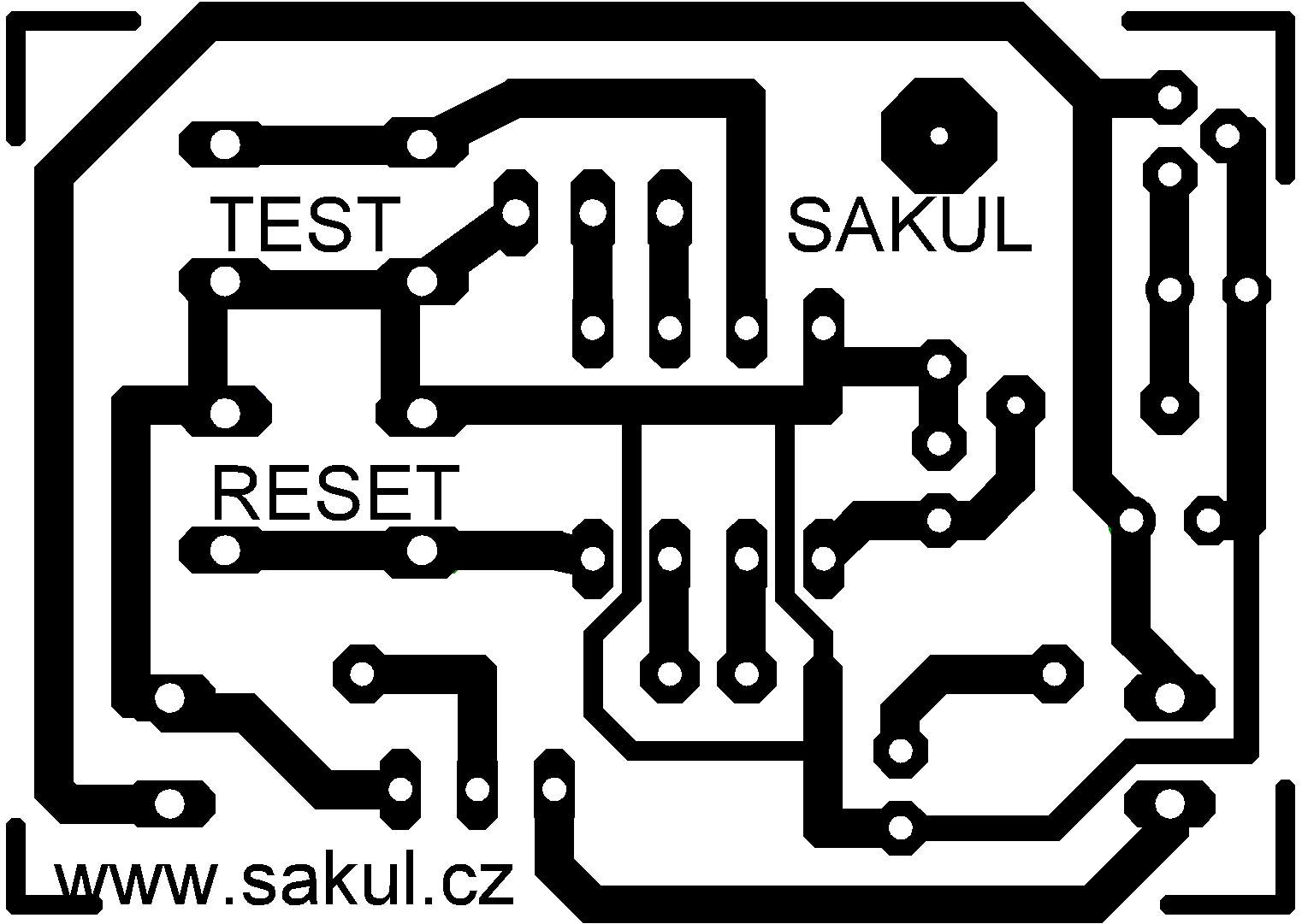
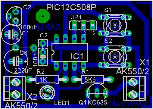
The PCB is a single-sided 43x30 mm board. One wire jumper must be fitted. Assembly should be straightforward; pay attention to traces routed between the microcontroller pins to avoid accidental bridges.
Operation
After power is applied, the processor initializes and LED1 flashes five times. The processor then powers the PIR module. PIR modules usually need 30-60 seconds to stabilize, so the controller is not active during that time.
Once active, the controller waits for a signal from the PIR module or S1. Standby is indicated approximately every 10 seconds by a short flash of LED1. When a signal arrives, Q1 and therefore the motor are activated for 350 ms, releasing the trap mechanism.
After activation, PIR power is disconnected and LED1 indicates triggered state approximately every 10 seconds by three short flashes. The trap can be returned to standby by pressing S2, which resets the processor. The prototype was powered from a small 12 V / 1.3 Ah gel battery and could run for several weeks.
PIR Module
The PIR module used in the original construction required about 4.8-12 V. Because of that, a 4.5 V flat battery could not be used directly and the 78L05 regulator had to stay in the circuit, even though it draws about 3 mA. The used PIR module also had an active-high output, so it had to be inverted using an optocoupler.
Modern PIR modules are available with 2.5-5.5 V supply and around 40 uA consumption, which is much better for this construction. With such a module, the voltage regulator can be omitted, a 4.5 V battery can be used and total current can be reduced to roughly 450 uA. This approach was planned for the second controller version.
Suitable examples include miniature PIR modules such as PSL31 with 3-5.5 V supply, 120 uA consumption and 14x15 mm size, or PM321 with 2.6-5 V supply and about 35 uA current.
Bill of Materials
| Designator | Qty | Value / Type | Note |
|---|---|---|---|
R1 | 1 | 5.6K | |
R2 | 1 | 1K | |
C1 | 1 | 100uF/10V | |
C2 | 1 | 100nF | |
C3 | 1 | 220uF/16V | |
LED1 | 1 | Red 3mm 2mA LED | |
IC1 | 1 | PIC12F508 | Programmed microcontroller. |
IC2 | 1 | 78L05 | Regulator. |
S1, S2 | 2 | PCB micro button | |
JP1 | 1 | 3-pin breakable jumper header | |
X1, X2 | 2 | ARK550 2x2-pin PCB terminal block |
Documentation
The documentation package contains construction files, Eagle project and firmware for the microcontroller.
Configuration
| Configuration directive | __CONFIG _MCLRE_ON & _CP_OFF & _WDT_OFF & _IntRC_OSC |
|---|
Declaration
This construction is original work and may not be republished on other websites or used commercially without my permission. Linking to this website and this construction is allowed. I assume no responsibility for the behavior of the device or for any damage caused by its use. The device is intended only for personal use.
This construction uses microcontroller firmware protected by copyright. A free license is granted for personal use. Any sale is not allowed without the author's permission.