Published in Praktická Elektronika 11/2011.
This project is a digital stopwatch originally built for SDH Dobšín - Kamenice fire brigade training. The circuit is designed for measuring an attack run with two targets, but it can be adapted for other timing tasks as well.
Main Features
| 1 | Time measurement on a six-digit display in the 99:59:99 format: minutes, seconds and hundredths. |
|---|---|
| 2 | Up to five split times and two final target times can be stored. |
| 3 | Measurement stops using two end switches with selectable NC/NO contact logic. |
| 4 | Measured times can be browsed after the run ends. |
| 5 | Measured values can be sent to a PC through RS232 and a Cannon 9M connector. |
| 6 | Simple single-button operation. |
| 7 | Wide supply range: 8-15 V AC/DC, about 100 mA, powered from a car battery, battery pack or mains adapter. |
| 8 | Optically isolated inputs and optional internal supply for target sensors and the start button. |
| 9 | Operating temperature from -20 to +40 °C. |
| 10 | Protected by a 400 mA/F glass fuse. |
Processor Schematic
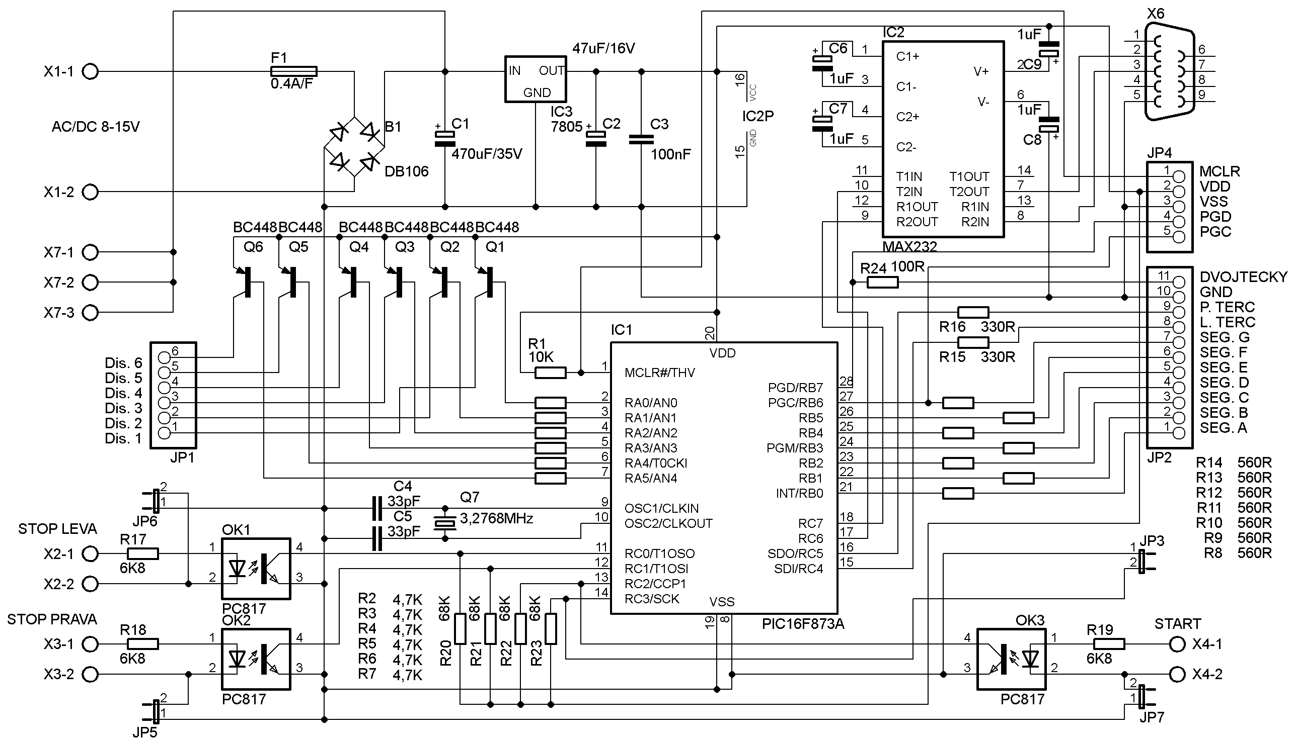
The stopwatch is split into two boards: processor board and display board. This schematic shows the processor section.
Display Schematic
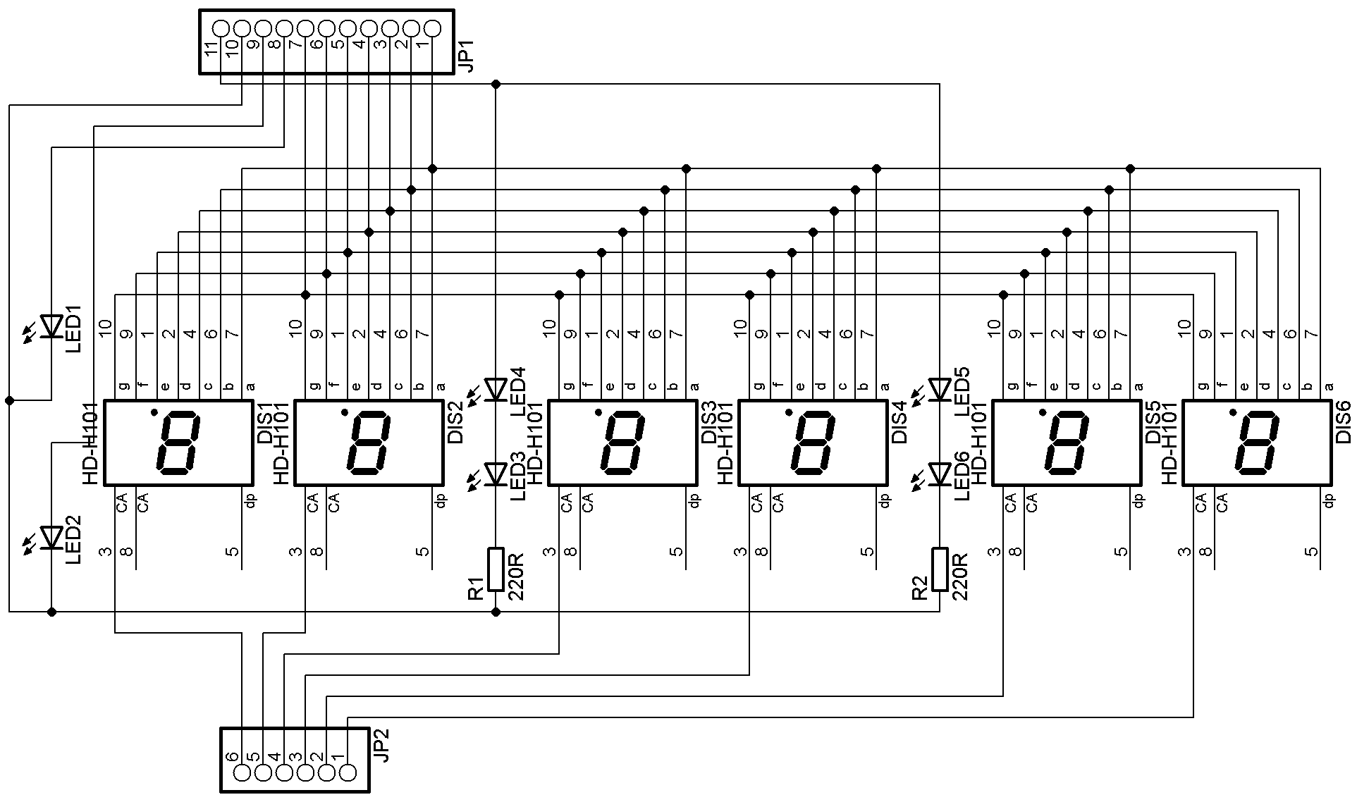
This schematic shows the display section of the stopwatch.
Processor PCB and Assembly
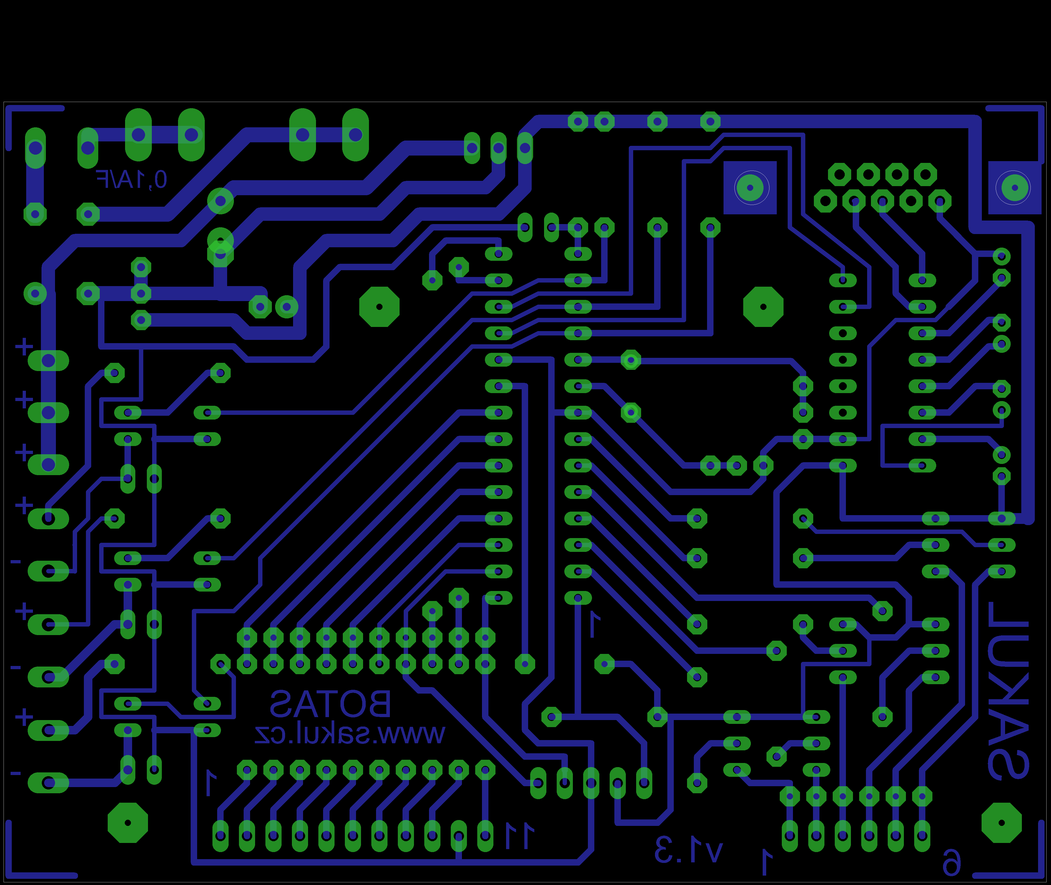
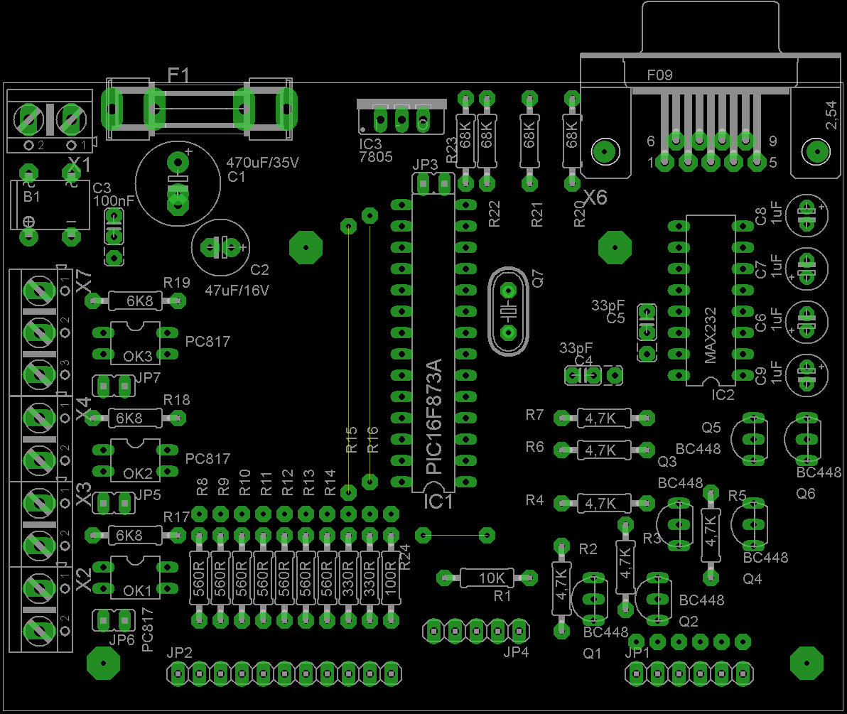
The processor PCB is a single-sided 100x75 mm board. Do not forget the three wire jumpers. The microcontroller may be soldered directly because it can be programmed in-circuit through JP4.
Display PCB and Assembly
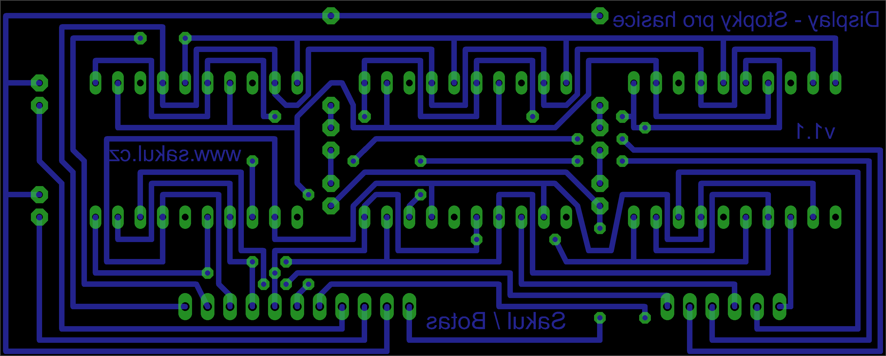
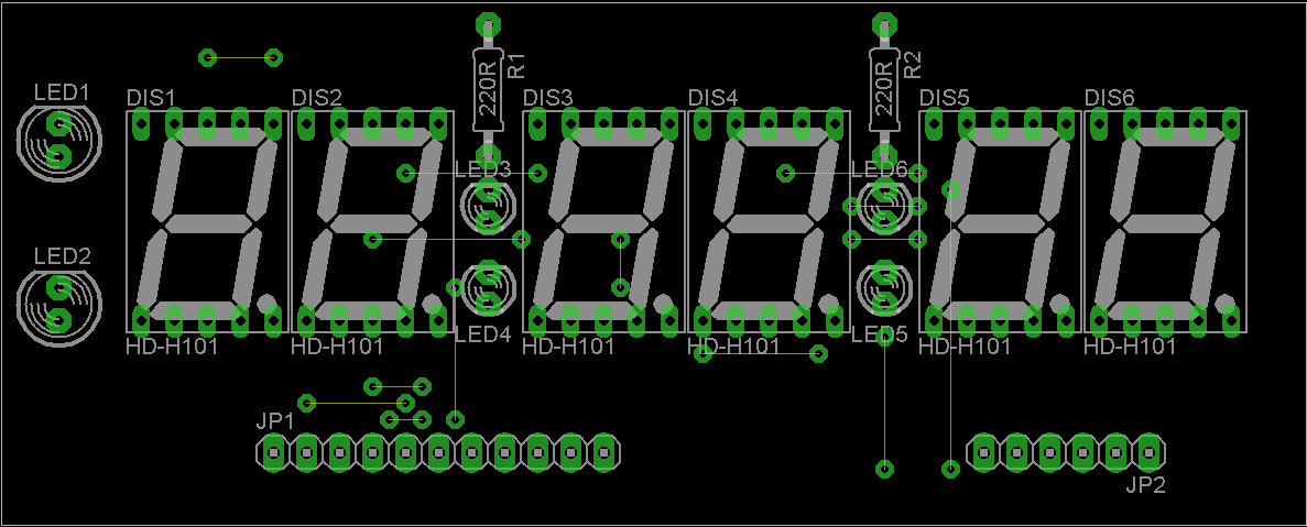
The display PCB is a single-sided 100x40 mm board. Pay special attention to the ten wire jumpers; two of them must be routed on the copper side.
Bring-Up and Settings
The device has practically no adjustment elements, so with careful assembly it should work on the first power-up. The main thing to watch is correct placement of wire jumpers, especially on the display board. The prototype was installed in a KM50 enclosure with red plexiglass on the front panel; the current version is intended for a KM60 enclosure and the outputs are adapted to it.
The only configuration is the contact type used on the end switches. Both NO and NC contacts are supported. For NO contacts, JP3 must be fitted. For NC contacts, JP3 is left open.
Jumpers JP5, JP6 and JP7 ground the cathodes of the optocoupler LEDs. With the jumpers fitted, the stopwatch internal supply can power the target sensors from terminal block X7-1 to X7-3. This is useful with mechanical switches. For maximum universality, the jumpers can be left open and the target electronics can use a separate supply. The optocouplers reliably detect 5-24 V signals; for other voltage levels, resistors R17, R18 and R19 must be changed.
Operation
The stopwatch is activated by connecting the supply voltage. If everything is correct, initialization runs and all display segments flash in sequence. The display then shows 00:00:00.
The device also checks whether the target sensors are ready for start. If the sensors are ready, red LEDs LED1 and LED2 in front of the display are lit. If a target sensor is in an incorrect position or configuration, the corresponding LED is off and the target or wiring must be checked. This depends on the JP3 input configuration.
Pressing START on X4-1 and X4-2 begins timing and turns off the target status LEDs. Pressing START during measurement stores a split time, up to five split times in total. Timing stops only after both target sensors are reached. At that moment the display briefly flashes and the times are sent to the PC.
After the run, short START presses browse through stored split times. Since measured times are usually in tens of seconds, the first two digits identify the split number. For example, 3-10:83 means split number 3. Final target times are displayed in full and identified by the corresponding target LED. Browsing can continue until the stopwatch is reset or power is lost. Reset is done by holding START for about 3 seconds.
PC Communication
The device can be connected to a PC for displaying and later processing measured values. No dedicated management application is provided, so data must be copied, stored and processed in other suitable programs.
The PC connection uses a Cannon 9 Female connector. The computer needs an RS232 serial port, ideally Cannon9M. If only Cannon25 is available, a common adapter can be used. If the PC has no serial port, a USB to RS232 converter can be used. Connector X6 is located on the rear side of the device.
The stopwatch is optimized for HyperTerminal, which was included in Windows XP. The documentation contains example settings, sample Stopky.txt data and a Stopky.ht configuration file. The COM port will likely need to be adjusted for the specific PC.
Possible Faults
The device was designed with simple operation and safe handling in mind. Supply polarity does not matter and the device can even operate from AC voltage. The supply range is 8-15 V.
The most likely fault is a blown fuse caused by a short circuit on connected peripherals. A 0.16 A to 0.400 A fast fuse may be used. No other common faults should normally occur.
Bill of Materials
Processor Board
| Designator | Qty | Value / Type | Note |
|---|---|---|---|
R1 | 1 | 10K | |
R2-R7 | 6 | 4.7K | |
R8-R14 | 7 | 560R | |
R15, R16 | 2 | 330R | |
R17-R19 | 3 | 10K | |
R20-R23 | 4 | 68K | |
R24 | 1 | 100R | |
C1 | 1 | 470uF/35V | |
C2 | 1 | 47uF/10V | |
C3 | 1 | 100nF | |
C4, C5 | 2 | 33pF | |
C6-C8 | 3 | 1uF/50V | |
IC1 | 1 | PIC16F873A | Programmed microcontroller. |
IC2 | 1 | MAX232 | |
IC3 | 1 | 7805 | With heatsink. |
Q1-Q6 | 6 | BC448 | KC308 or similar. |
Q7 | 1 | 3.2768MHz crystal | |
OK1-OK3 | 3 | PC817 | Optocouplers. |
F1 | 1 | 400mA/F glass fuse | Including PCB holder. |
B1 | 1 | DB106 | Or similar 1A bridge. |
JP1-JP7 | 7 | Breakable jumper header | |
X1-X4 | 4 | 2-pin PCB terminal block | |
X6 | 1 | Cannon 9 Female | See text. |
X7 | 1 | 3-pin PCB terminal block |
Display Board
| Designator | Qty | Value / Type | Note |
|---|---|---|---|
R1, R2 | 2 | 220R | According to LEDs. |
LED1, LED2 | 2 | Red 5mm | |
LED3-LED6 | 4 | Red 3mm | |
DIS1-DIS6 | 6 | HD-H101 | Alternative SA56-11SRWA. |
JP1, JP2 | 2 | Breakable jumper header | Or short connection wires. |
Documentation - Updated 2015-06-20
The documentation package contains all construction files, Eagle project and firmware for the microcontroller.
Changes
| 2015-03-13 | Added a video showing installation of the USB-RS232 HL-340 converter driver. |
|---|---|
| 2015-03-14 | Updated documentation, Eagle project and the web guide. |
| 2015-06-20 | Updated stopwatch firmware to version 1.21B, which no longer requires line wrapping/new line handling in HyperTerminal. A firmware version that displays only final times and no split times was also added. |
Configuration
| Configuration directive | __CONFIG _CP_ALL & _WDT_OFF & _BODEN_OFF & _PWRTE_ON & _XT_OSC & _WRT_OFF & _LVP_OFF & _CPD_ON |
|---|
Bug Fixes
2013-04-16 - Fixed a bug with the first final time. Current firmware versions are 1.2A and 1.2B. More information is available in the discussion.
Declaration
This construction is original work and may not be republished on other websites or used commercially without my permission. Linking to this website and this construction is allowed. I assume no responsibility for the behavior of the device or for any damage caused by its use. The device is intended only for personal use.
This construction uses microcontroller firmware protected by copyright. A free license is granted for personal use. Any sale is not allowed without the author's permission. Since I am not the author of this firmware, it is published here with the consent of its author Botas.