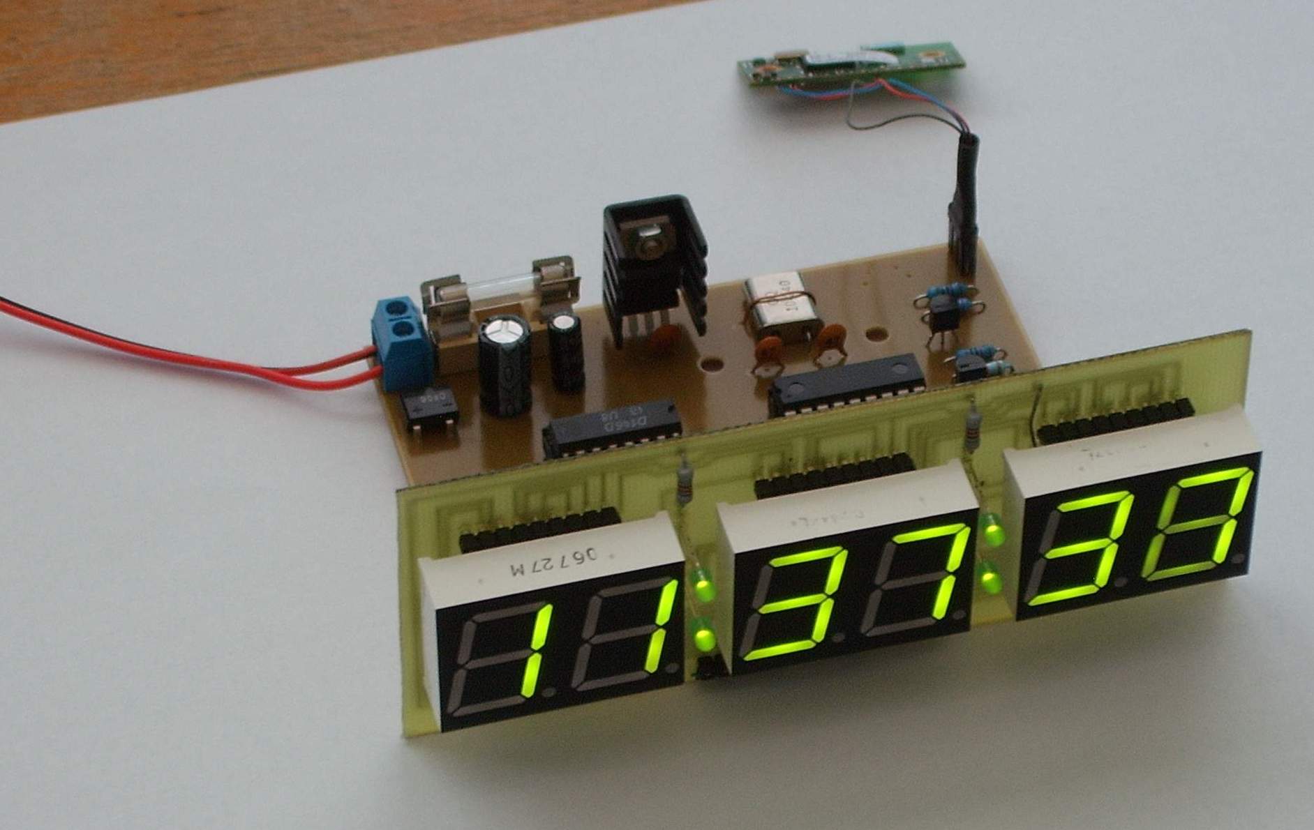
This project was created after practical problems with DCF clock synchronization. DCF clocks can set themselves automatically, but the long-wave signal is sensitive to interference and sometimes the clock could not synchronize for several days. Constantly searching for a better place for the receiver was not the kind of standalone operation I wanted.
The original idea was again a DCF-controlled clock, but with seconds and date display. After some discussion we arrived at a more interesting solution: use a GPS receiver instead of DCF. Since I had already experimented with GPS receivers, the direction was clear.
The clock uses a COMPASS NAVIBE GB337 GPS receiver with its own battery and Bluetooth 2.0 interface. The NMEA output format is easy to parse and the receiver was able to occasionally see at least one satellite even in a basement. For a clock, one satellite is enough to obtain accurate time, even though it would not be enough for normal position calculation.
Communication between the GPS receiver and the clock was solved using a Bluetooth module from connectBlue, represented locally by Spezial Electronic. The module used here is OEMSPA310. The module is self-contained and can be connected to the GPS clock processor with only minor interface circuitry.
Processor Schematic
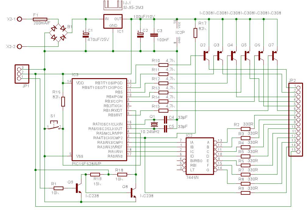
The whole construction is split into two parts: processor board and display board. This schematic shows the processor section.
Display Schematic
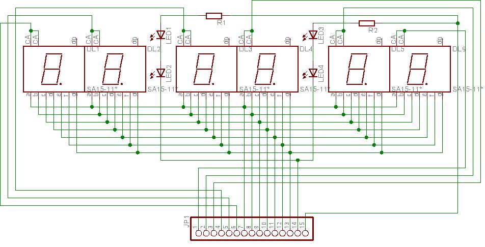
This schematic shows the display section.
Processor PCB and Assembly
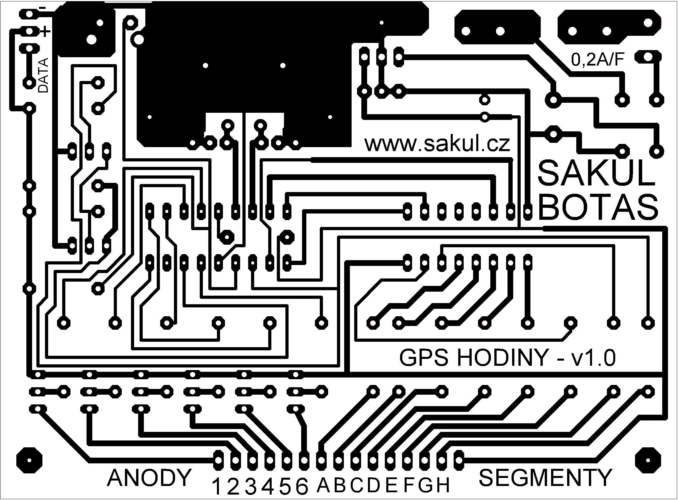
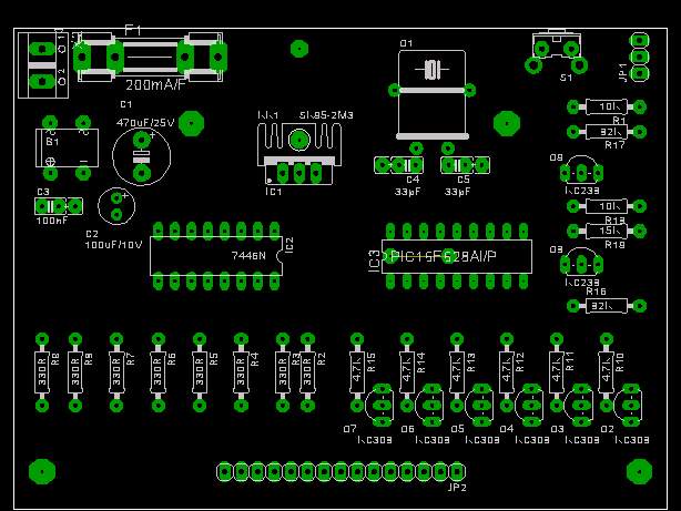
The processor PCB is a single-sided 100x74 mm board. Assembly should be straightforward; do not forget the wire jumper under IC3.
Display PCB and Assembly
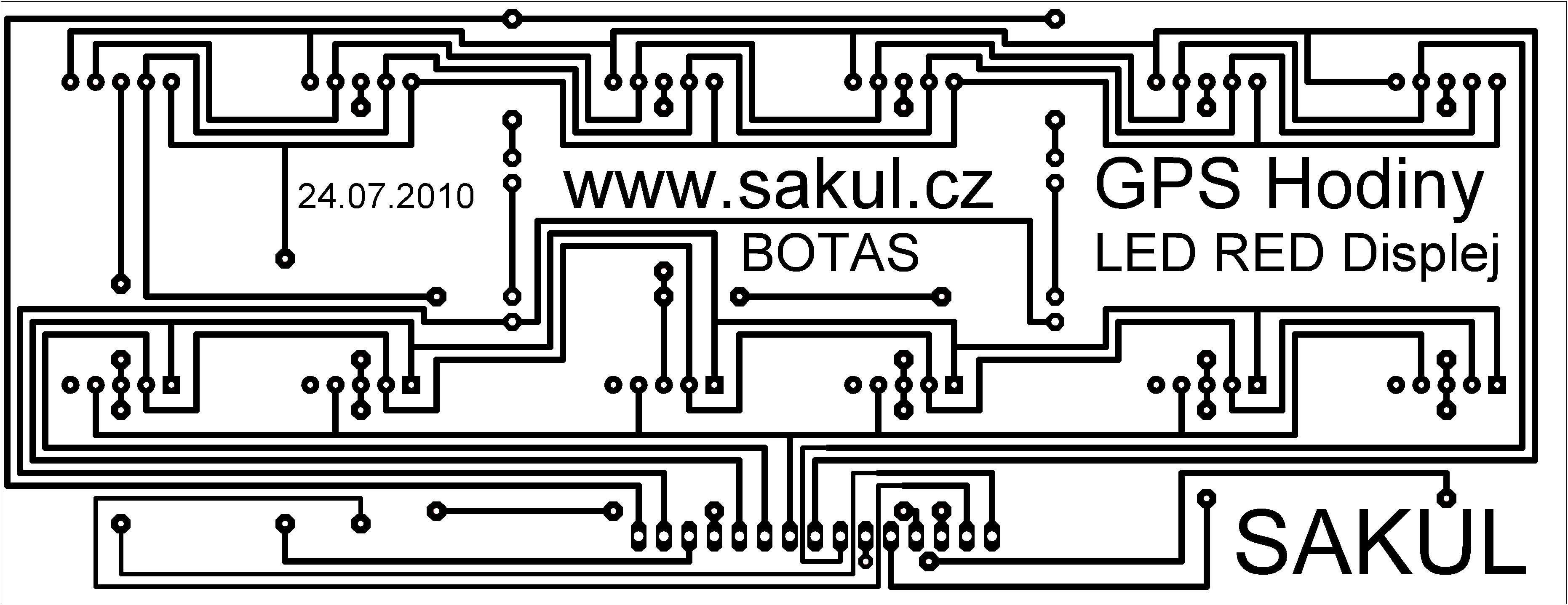
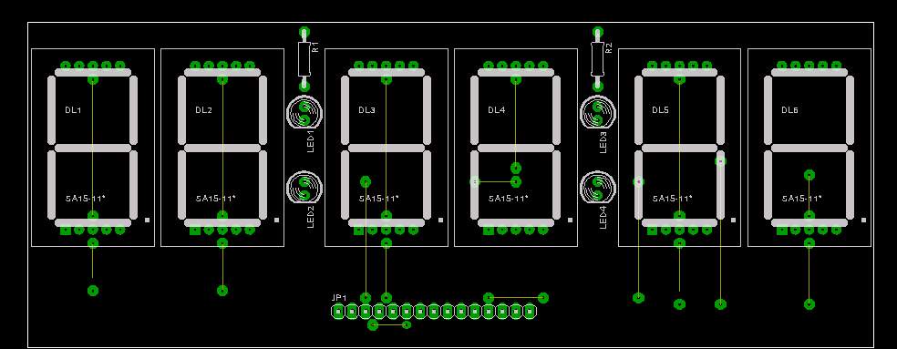
The display PCB is a single-sided 157x60 mm board. Pay attention to the wire jumpers: there are 11+6 of them. The six additional jumpers connect segment anodes and often do not need to be fitted because they are already connected inside the display. The display board pin order is mirrored relative to the processor board.
Bring-Up and Settings
The circuit does not require adjustment and works immediately after power is applied. The only value that may need tuning is the resistor value for the selected LED displays, especially R2-R9. The Bluetooth module also has to be configured so it can communicate with the GPS receiver.
Operation
The clock has a single button with two functions. A short press displays the current date in DD:MM.YY format. After about five seconds the display returns to the normal time mode.
A long press of about three seconds switches between summer and winter time. This has to be done manually. The clock remembers the last selected mode even after a power loss and restores it after power returns.
No other settings are required. The clock is synchronized automatically from GPS time. Only one satellite is needed for correct time information, so the receiver placement is not very critical. Because the GPS receiver communicates over Bluetooth, it can be placed several tens of meters away from the clock in a location with better reception.
The design is built around a PIC16F628A microcontroller. The display is driven by a 7446 decoder, or the older D146D can be used. Power is supplied through a bridge rectifier and voltage regulator, which makes the input polarity tolerant and also allows using an AC adapter. The regulator needs a small heatsink.
The Bluetooth module uses 3.3V logic, while the processor uses 5V logic. A simple transistor level converter made from Q8, Q9 and surrounding resistors was therefore added. The Bluetooth module is connected with three wires: supply +, supply - and TX data output connected to JP1.
A different GPS module with RS232 output could also be connected directly to JP1 instead of the Bluetooth module, which would reduce the overall cost.
Bluetooth Module Setup
The OEMSPA310 module has to be paired with the GPS receiver using the Basic Wizard software included with the module and also in the project documentation. During configuration the GPS receiver must be switched on so the module can find and pair with it.
The important values are the NAVIBE GB337 PIN code 0000, communication speed 38400 B/s and Flow Control set to NONE. I also enabled the option to configure the OEMSPA310 module directly over Bluetooth, which may be useful later. The first configuration must be performed over a cable.
The following video shows what the GPS receiver actually sends:
Possible Faults
The clock should currently work without problems. Older firmware versions had stability problems and the clock could occasionally freeze and require a restart.
Bill of Materials
Processor Board
| Designator | Qty | Value / Type | Note |
|---|---|---|---|
R1 | 1 | 10K | |
R2-R9 | 8 | 330R | According to the selected LED displays. |
R10-R15 | 6 | 4.7K | |
R16, R17 | 2 | 82K | |
R18 | 1 | 10K | |
R19 | 1 | 15K | |
C1 | 1 | 470uF/25V | |
C2 | 1 | 100uF/10V | |
C3 | 1 | 100nF | |
C4, C5 | 2 | 33pF | |
Q1 | 1 | 10.240MHz crystal | |
Q2-Q7 | 6 | KC308 | Or similar PNP. |
Q8, Q9 | 2 | KC238 | Or similar NPN. |
B1 | 1 | DB106 | Or another 1A bridge. |
IC1 | 1 | 7805 | With heatsink. |
IC2 | 1 | 7446N | Or D146D. |
IC3 | 1 | PIC16F628A | Programmed microcontroller. |
F1 | 1 | 200mA/F fuse | Including PCB holder. |
JP1, JP2 | 2 | Breakable jumper header | |
S1 | 1 | 90° PCB button |
Display Board
| Designator | Qty | Value / Type | Note |
|---|---|---|---|
RR1, R2 | 2 | 100R | Or according to used LEDs. |
LED1-LED4 | 4 | Red 5mm LED | |
DL1-DL6 | 6 | BS-AA11RD | Or another common-anode display. |
Documentation
The documentation package contains construction files, Eagle project and firmware for the microcontroller.
Declaration
This construction is original work and may not be republished on other websites or used commercially without my permission. Linking to this website and this construction is allowed. I assume no responsibility for the behavior of the device or for any damage caused by its use. The device is intended only for personal use.
This construction uses microcontroller firmware protected by copyright. A free license is granted for personal use. Any sale is not allowed without the author's permission. Since I am not the author of this firmware, it is published here with the consent of its author Botas.