This construction was published in Praktická elektronika 2/2015.
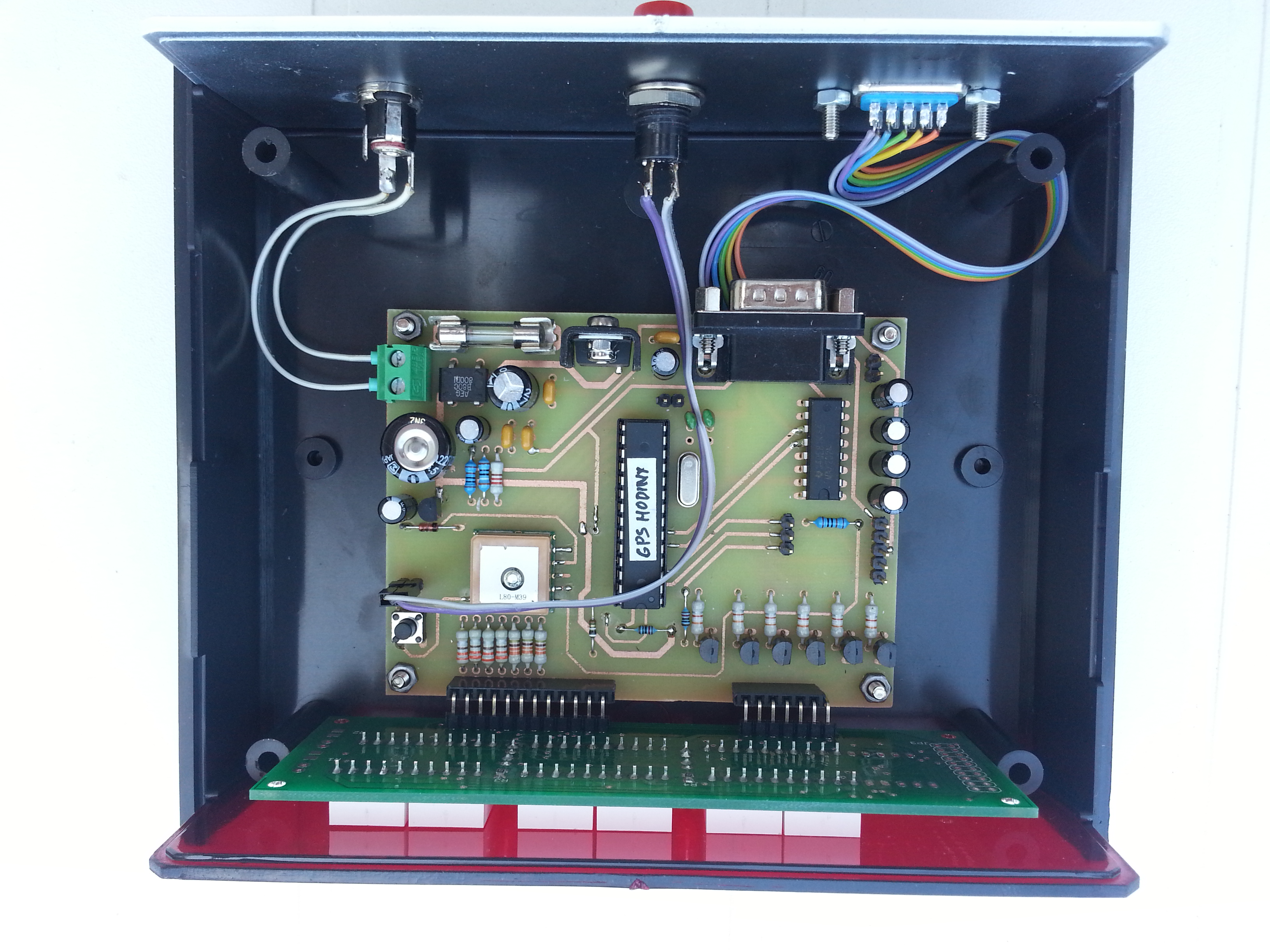
This is the second version of the GPS-controlled clock. The first version proved that a GPS receiver is very convenient for a self-setting clock, so this version focuses on a cleaner board design, easier use of available GPS modules and practical support for RS232 or Bluetooth serial data.
The clock is built around a PIC16F628A microcontroller and a six-digit LED display. Time is received from a GPS receiver in NMEA format. For clock synchronization, a single satellite is enough because the unit needs accurate time, not position.
Technical Specifications
| Supply | 8-15 V DC or AC adapter through a bridge rectifier. |
|---|---|
| Microcontroller | PIC16F628A. |
| Display | Six common-anode LED displays. |
| Display driver | 7446N or older D146D. |
| Time source | GPS receiver with NMEA output. |
| Communication | RS232/TTL or Bluetooth module configured as serial port. |
| Controls | One button for summer/winter time switching. |
| External display | Prepared output for an external display. |
Processor Schematic
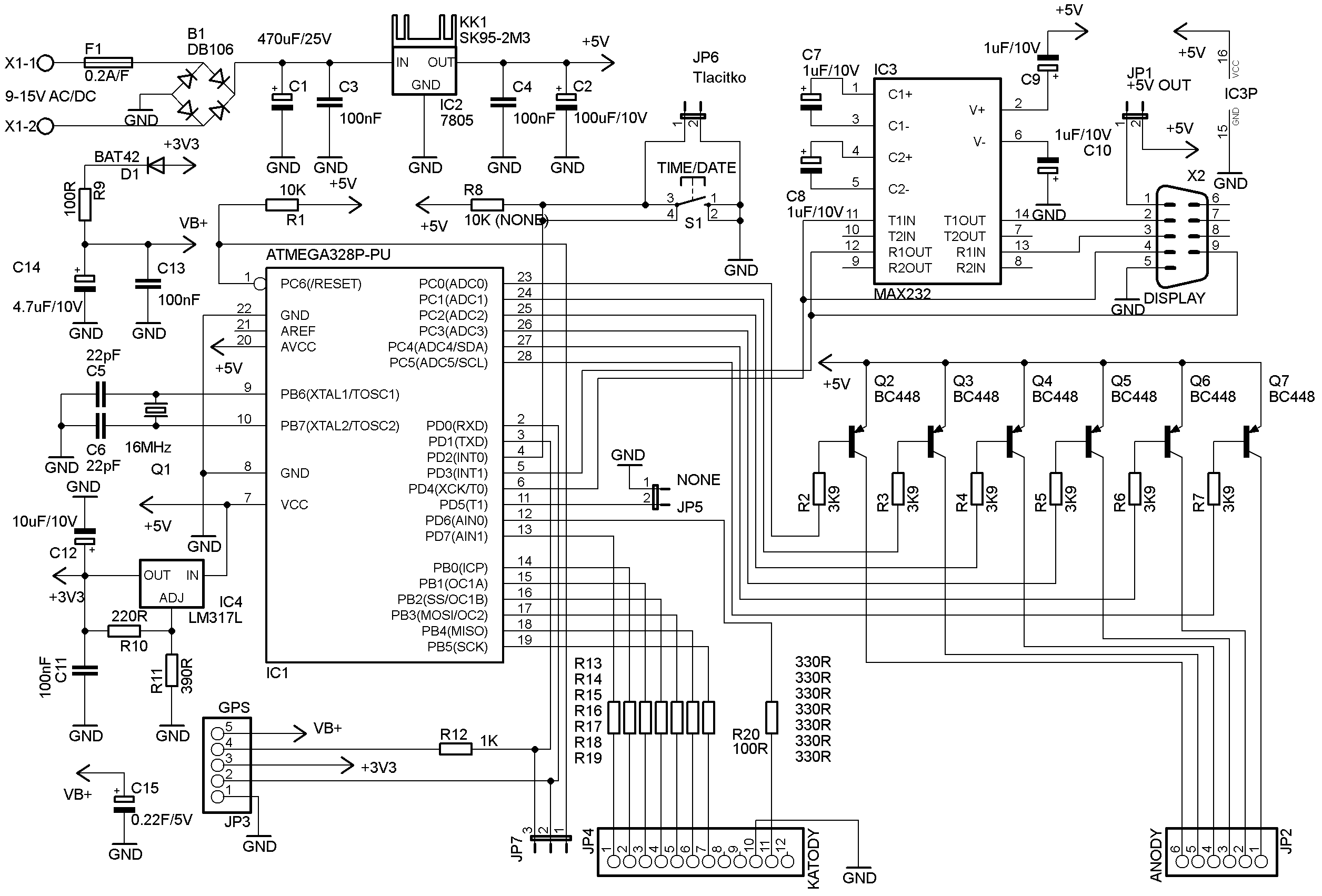
The construction is split into processor and display boards. The processor board contains the PIC16F628A, display driver, power supply, GPS data input and connectors for the display board.
Display Schematic
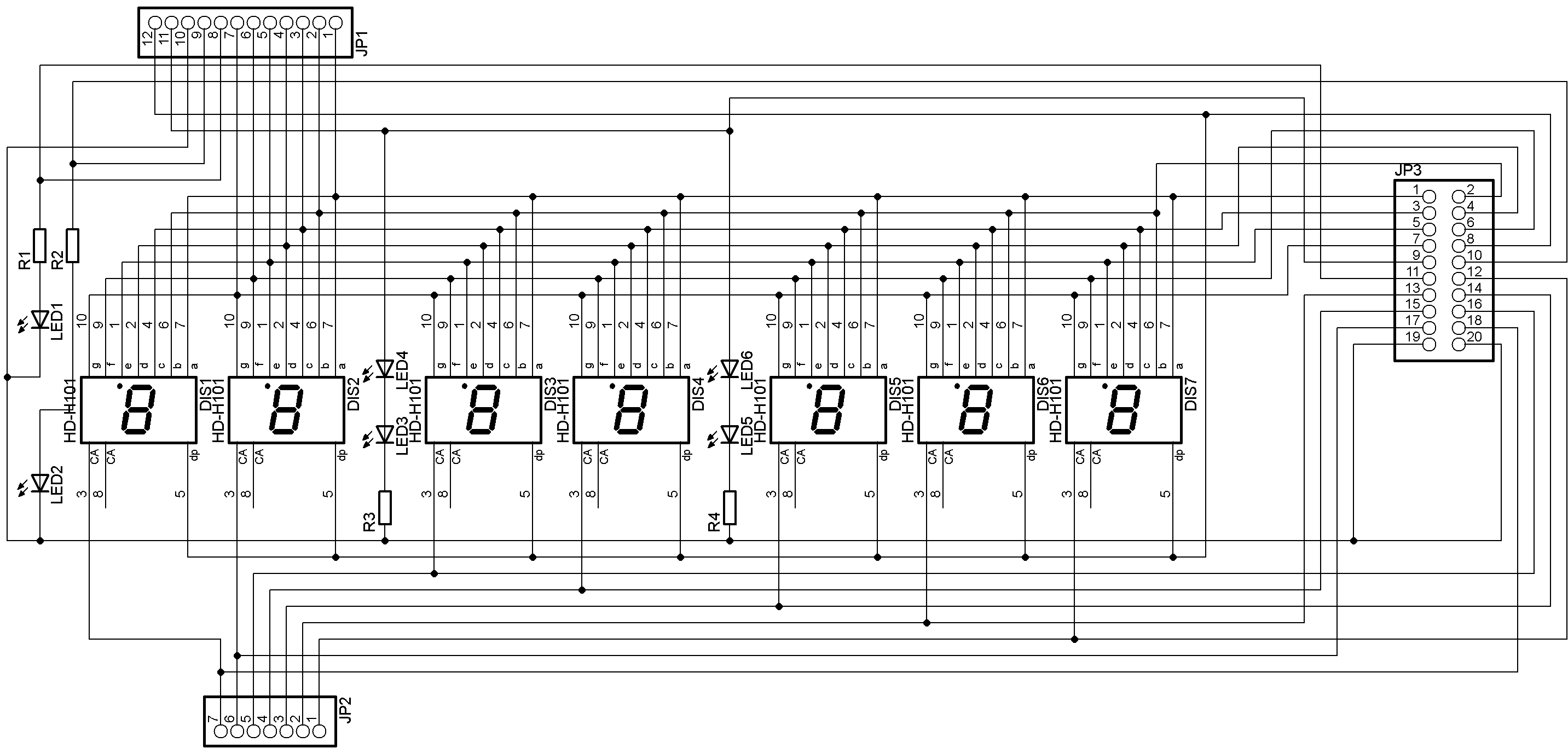
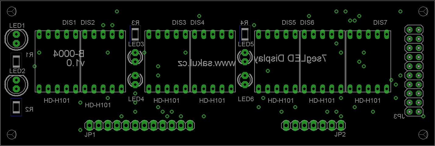
The display board carries the LED displays and indicator LEDs and connects to the processor board with a flat cable.
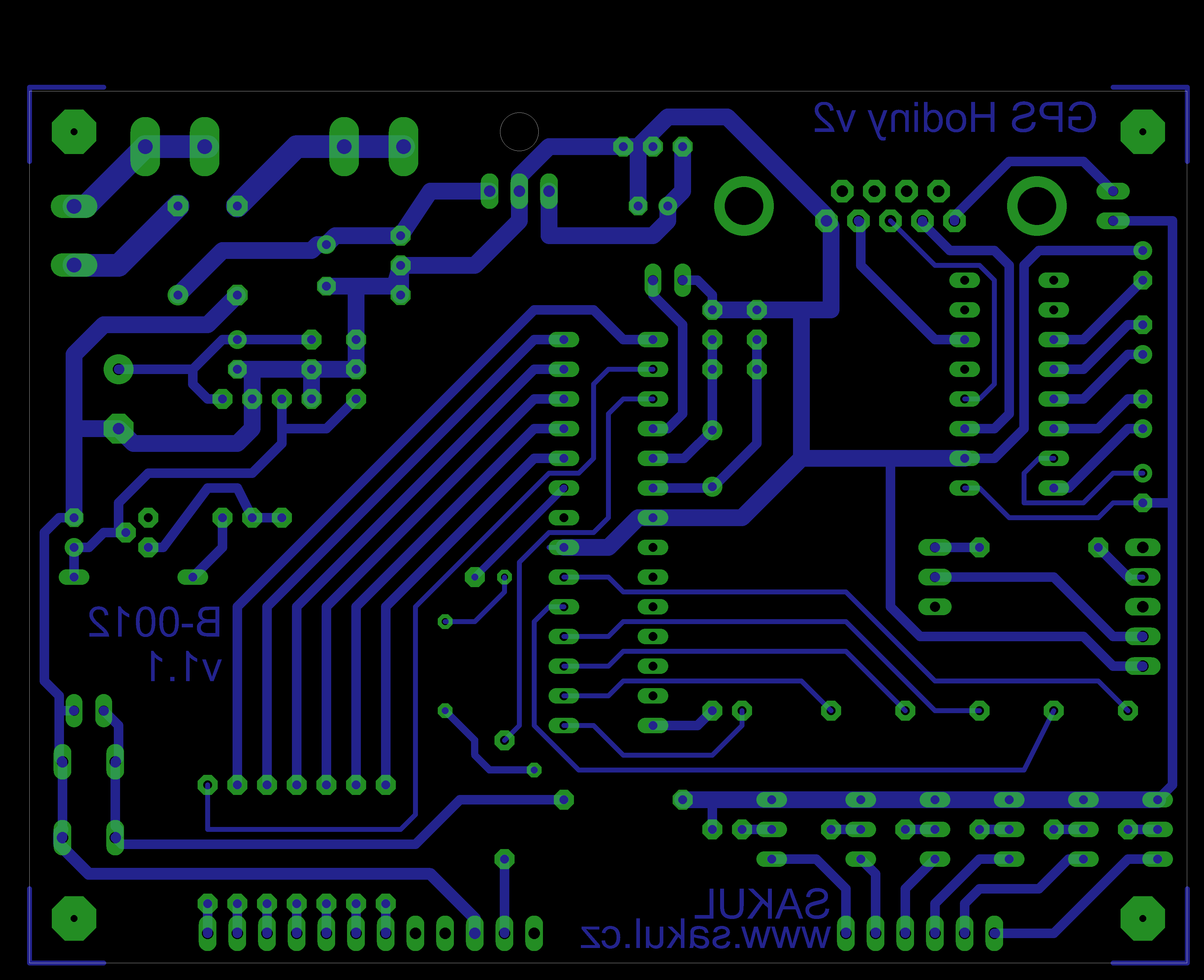
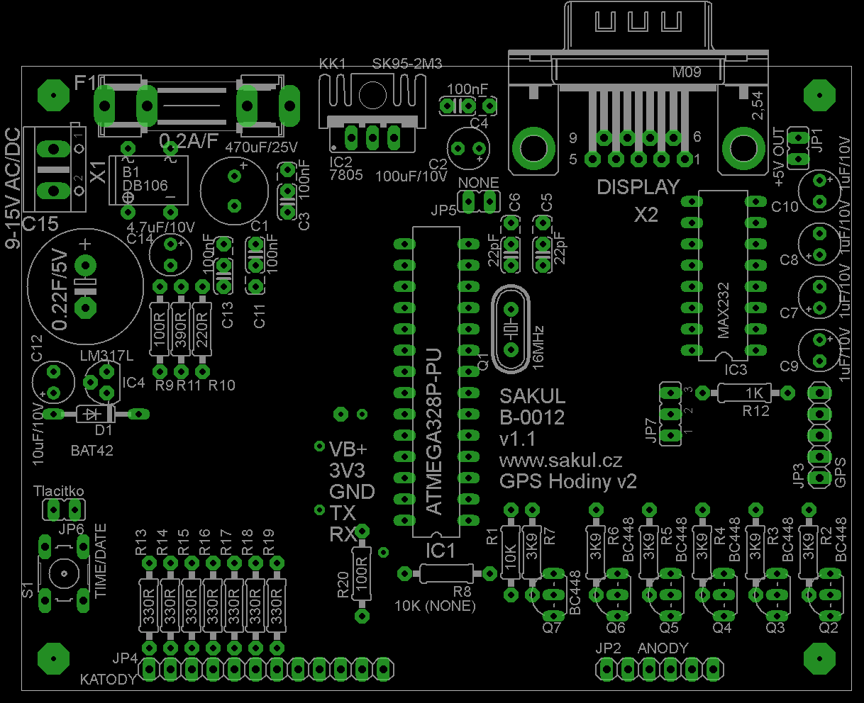
Processor PCB and Placement
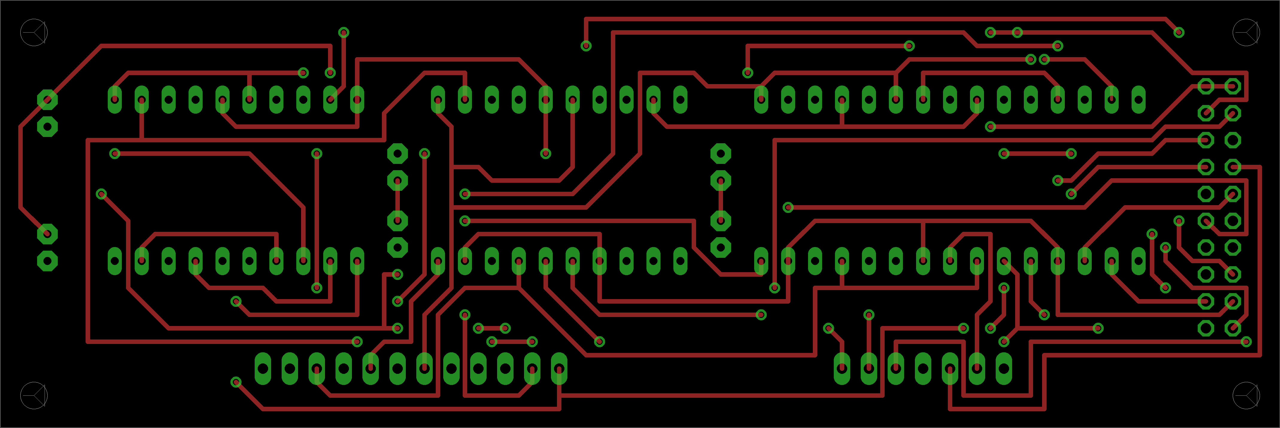
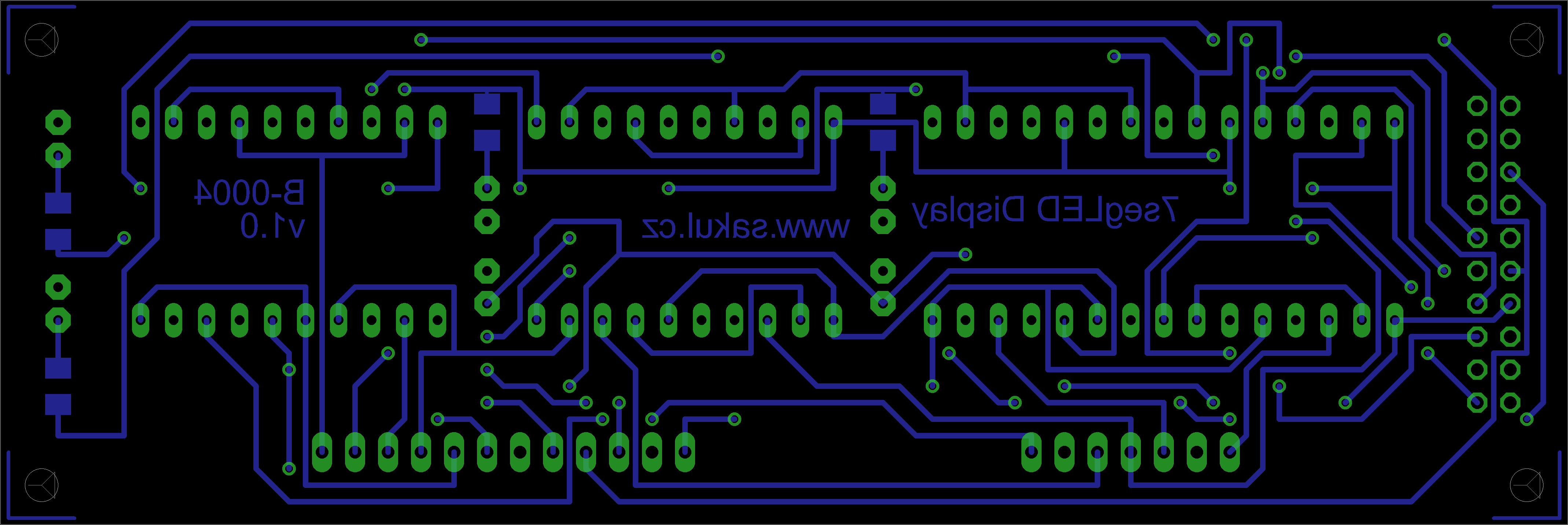
Display PCB and Placement
GPS Receiver and Function
The clock requires a GPS receiver that sends NMEA time data. Modules with TTL serial output can be used directly if their voltage levels match the clock input. RS232 modules or 3.3 V Bluetooth modules may require a simple level converter. Bluetooth receivers can be paired with a serial Bluetooth module and used as a wireless serial link.
After power-up, check the 5 V supply first, then connect the GPS receiver and display. Once valid NMEA data is received, the clock starts showing the current time. If the time does not appear, check receiver power, baud rate, voltage levels and whether the receiver sends the expected NMEA sentences.
Controls and External Display
The clock is controlled by the S1 TIME/DATE button. Date display is not supported in this version, so the button switches summer and winter time. The selected offset is saved in the processor EEPROM and survives power loss.
The design also includes signals for an external display. This can be useful when the electronics and the visible display should be placed separately.
Bill of Materials
Processor Board
| Designator | Qty | Value / type | Note |
|---|---|---|---|
R1 | 1 | 10K | |
R2-R9 | 8 | 330R | According to display type. |
R10-R15 | 6 | 4.7K | |
R16, R17 | 2 | 82K | |
R18 | 1 | 10K | |
R19 | 1 | 15K | |
C1 | 1 | 470uF/25V | |
C2 | 1 | 100uF/10V | |
C3 | 1 | 100nF | |
C4, C5 | 2 | 33pF | |
Q1 | 1 | 10.240 MHz crystal | |
Q2-Q7 | 6 | KC308 | Or similar PNP. |
Q8, Q9 | 2 | KC238 | Or similar NPN. |
B1 | 1 | DB106 | Or another 1A bridge. |
IC1 | 1 | 7805 | With heatsink. |
IC2 | 1 | 7446N | Or D146D. |
IC3 | 1 | PIC16F628A | Programmed processor. |
F1 | 1 | 200mA/F fuse | With PCB holder. |
JP1, JP2 | 2 | Pin header | |
S1 | 1 | 90° PCB button |
Display Board
| Designator | Qty | Value / type | Note |
|---|---|---|---|
R1, R2 | 2 | 100R | Or according to LEDs. |
LED1-LED4 | 4 | 5 mm red LED | |
DL1-DL6 | 6 | BS-AA11RD | Or another common-anode display. |
Documentation - Updated 2015-11-01
The complete construction documentation is available for download. It includes the Eagle project and microcontroller firmware.
Update
| 2015-10-30 | v1.1 - Added the option to enable or disable colon blinking using internal jumper JP5. The updated firmware is included in the documentation package. |
|---|
Declaration
This construction is original author work. Republishing on other websites or commercial use is not permitted without the author's permission. Linking to this page is allowed. The device is intended for personal use only.
The microcontroller firmware is protected by copyright and is provided free of charge for personal use. Sale or commercial use is not allowed without the author's permission.