This laser beam gate was designed for use with fire-brigade stopwatches. Many laser gate circuits can be found online, but most of them are intended for security systems and are not very suitable for this timing application. This version uses a dedicated microcontroller program for stopwatch triggering and adds several practical functions.
Basic Specifications
| Supply voltage | 8-15 V DC. |
|---|---|
| Current consumption | Approximately 60 mA. |
| Maximum relay contact current | 150 mA. |
| Beam indication | Uninterrupted beam is indicated by a red LED. |
| Relay indication | Relay activation is indicated by a yellow LED. |
| Power indication | Supply voltage is indicated by a green LED. |
| Protection | Reverse-polarity protection. |
| Laser modes | Static / pulse. Pulse mode is not supported yet. |
| Evaluation modes | Stopwatch / security. Security mode is not supported yet. |
Schematic
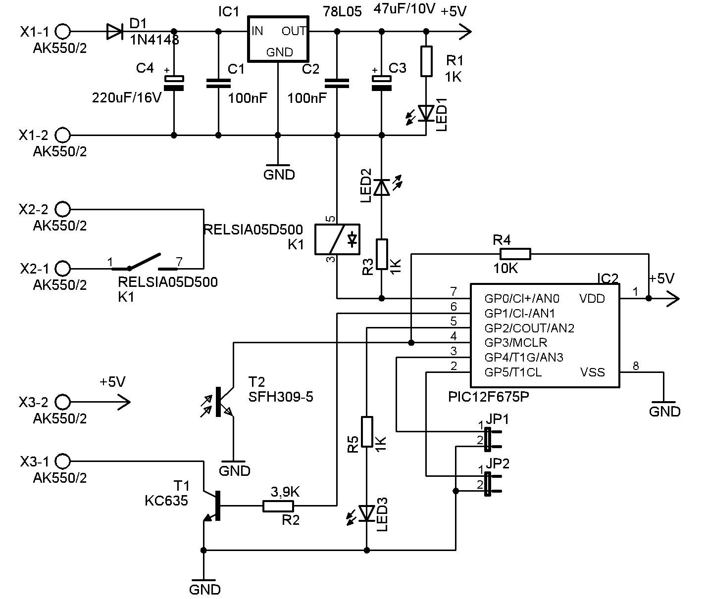
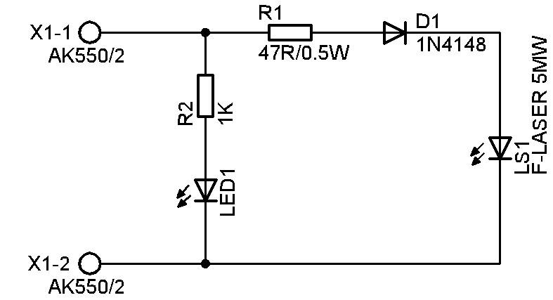
The circuit is intentionally simple. The core is a PIC12F675 microcontroller, so only a small number of additional components is required. The schematic shows the complete connection of both the receiver and transmitter modules.
Description and Function
The laser gate consists of two main parts: transmitter TX and receiver RX. They are connected by a two-wire cable up to about 30 m long. The transmitter contains the laser module, a green LED indicating laser power and the static / pulse mode connection. The receiver switches power for the transmitter through T1 and evaluates the returned laser beam through T2.
When the beam is uninterrupted, red LED3 on the receiver is on. IC1 78L05 provides the regulated supply and D1 protects the circuit against reversed polarity. After power-up, if the beam is uninterrupted, the gate enters idle state. Green LEDs on RX and TX are on and the red LED on RX indicates a valid beam.
When the beam is interrupted, the circuit generates a short one-second pulse that closes the relay contact. The pulse is indicated by a yellow LED flash. The length of the beam interruption does not matter; only one pulse is generated. If the beam remains interrupted for more than 15 seconds, another relay pulse is generated.
After the beam is restored, the red LED starts flashing quickly. This means the beam is present again, but another relay activation is temporarily blocked. This lockout lasts 15 seconds. Once the red LED stops flashing and stays on, the gate is ready for another trigger. This mode prevents unwanted repeated stopwatch triggering.
PCB and Component Placement
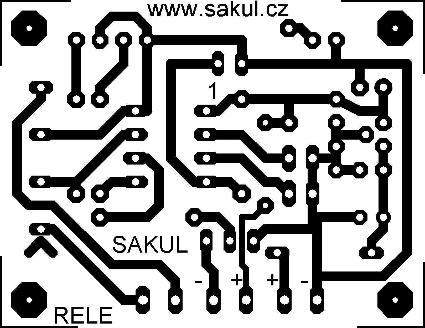
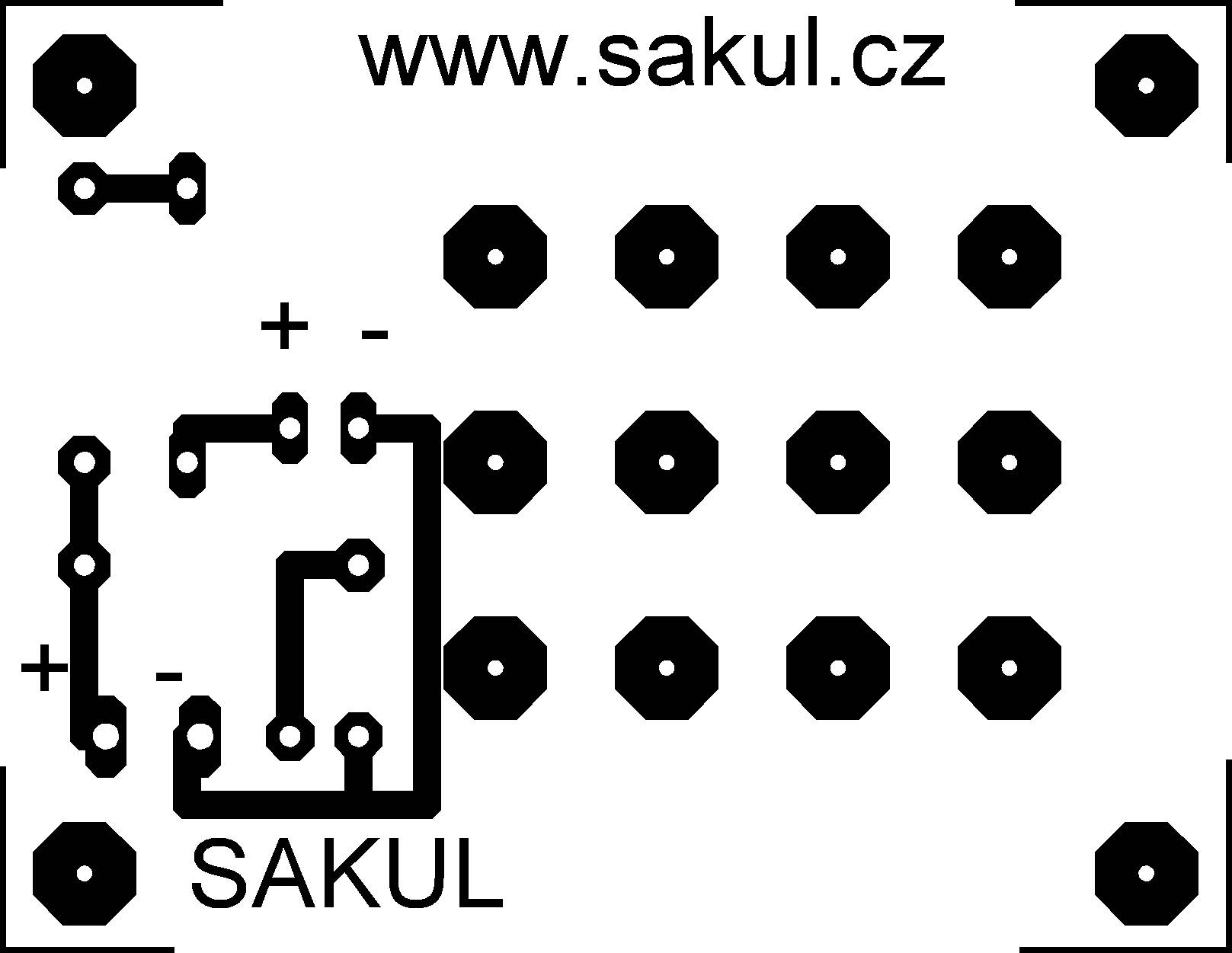
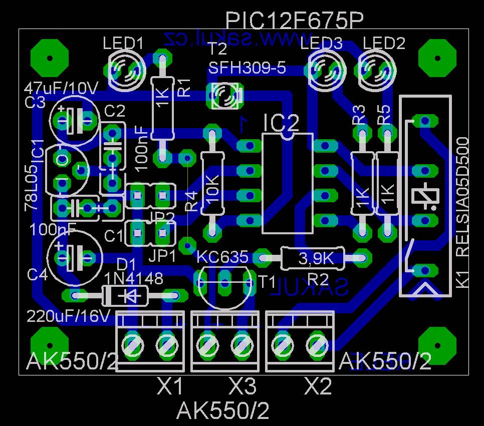
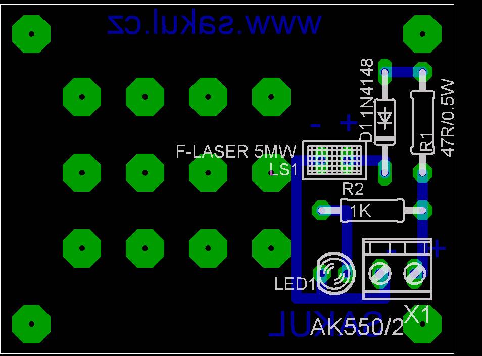
Both PCBs are single-sided boards, each 45x35 mm. Assembly should be straightforward; remember to fit the wire jumper on the RX board.
Bring-Up and Setup
The assembled TX and RX boards should be mounted into suitable enclosures. The TX enclosure needs an opening for the laser beam and the RX enclosure needs a matching opening. It is also useful to place a short tube, for example 7 mm in diameter and 25 mm long, over the receiver transistor. This improves protection against direct sunlight.
The receiver must always be mounted so that direct sunlight cannot hit the receiving transistor. Alignment is simple thanks to the visible laser beam and the red indicator LED on the receiver. The distance between TX and RX can be up to 30 m.
Documentation
The complete construction documentation is available for download. It includes the Eagle project and microcontroller program.
Configuration
| Configuration directive | __config _BODEN_OFF & _CP_ON & _CPD_ON & _PWRTE_ON & _WDT_OFF & _MCLRE_OFF & _INTRC_OSC_NOCLKOUT |
|---|
Declaration
This construction is original author work. Republishing on other websites or commercial use is not permitted without the author's permission. Linking to this page is allowed. The device is intended for personal use only and the author does not accept responsibility for damage caused by its use.
The construction uses microcontroller firmware protected by copyright. A free license is granted for personal use. Sale of the firmware or derived commercial use is not allowed without the author's permission.