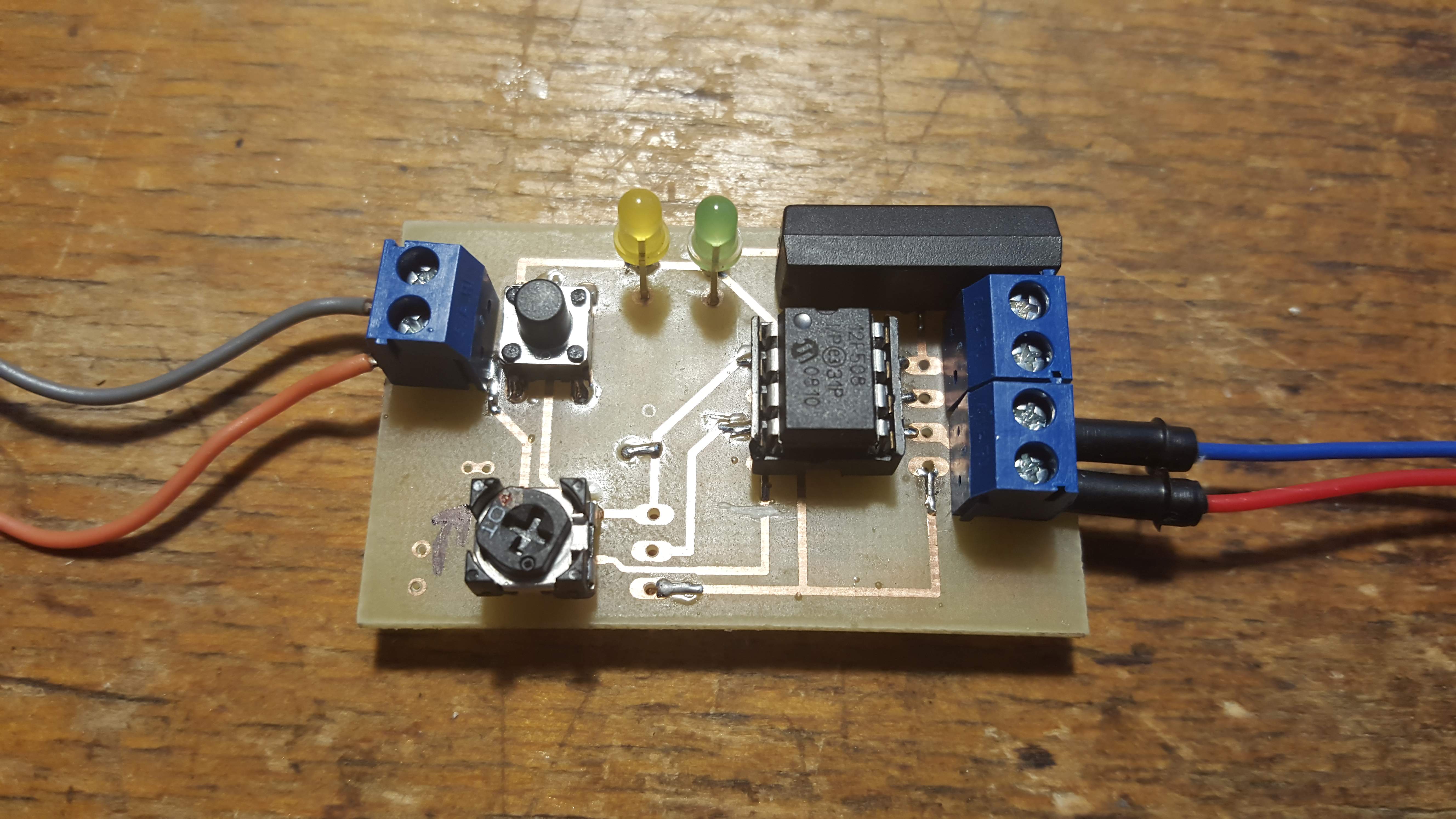
This construction was created after repeated requests for a device that could start stopwatches by evaluating the sound of a starting shot. The circuit continuously monitors sound level using an electret microphone and, when the adjusted threshold is reached, generates a short pulse that starts the stopwatch. The microphone input is then blocked for about 15 seconds, so another start pulse cannot be generated immediately. The generated start pulse lasts about 1 second, which prevents an unwanted reset of the stopwatch.
Technical Specifications
| Supply voltage | 8-15 V/DC |
|---|---|
| Current consumption | up to 20 mA with relay active |
| Maximum contact current | Relay 100 mA |
| Sensing element | Electret microphone |
| Ready indication | Green LED |
| Relay indication | Yellow LED |
Circuit
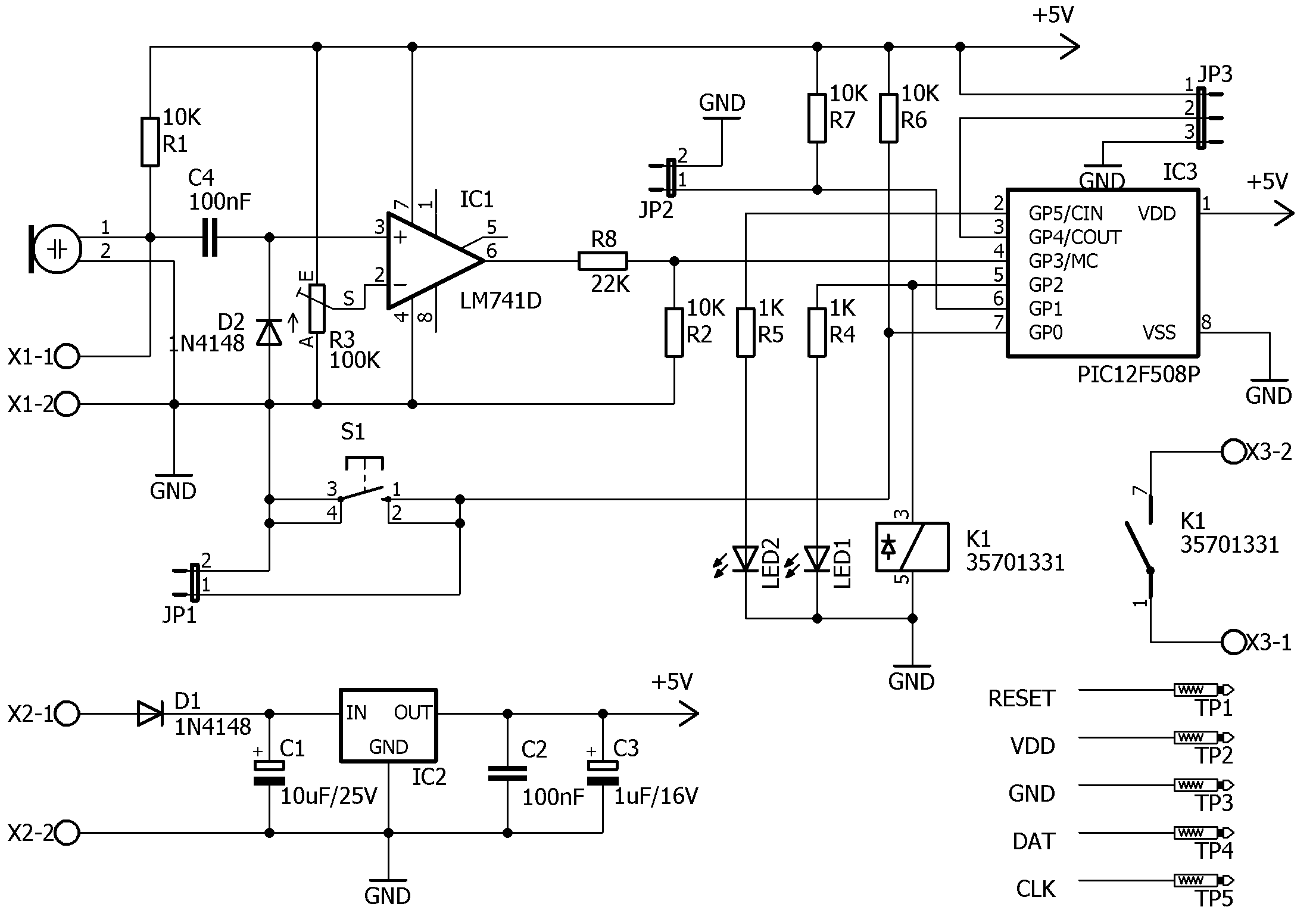
The circuit is relatively simple and consists of three main parts. Voltage regulator IC2 converts the 8-15 V/DC input voltage to 5 V. The input also includes diode D1, which protects the device against accidental reverse polarity. The remaining parts around the regulator are filtering capacitors C1-C3. The next part is the microphone circuit with IC1 LM741. It works as a comparator and compares the microphone voltage with a reference set by trimmer R3. The third part is the PIC12F508 microcontroller IC3, which performs the final evaluation. Using a microcontroller may seem unnecessary, but it makes future changes and improvements possible. For that reason the board also includes button S1, JP2 and JP3, which currently have no function.
Schematic
Printed Circuit Boards
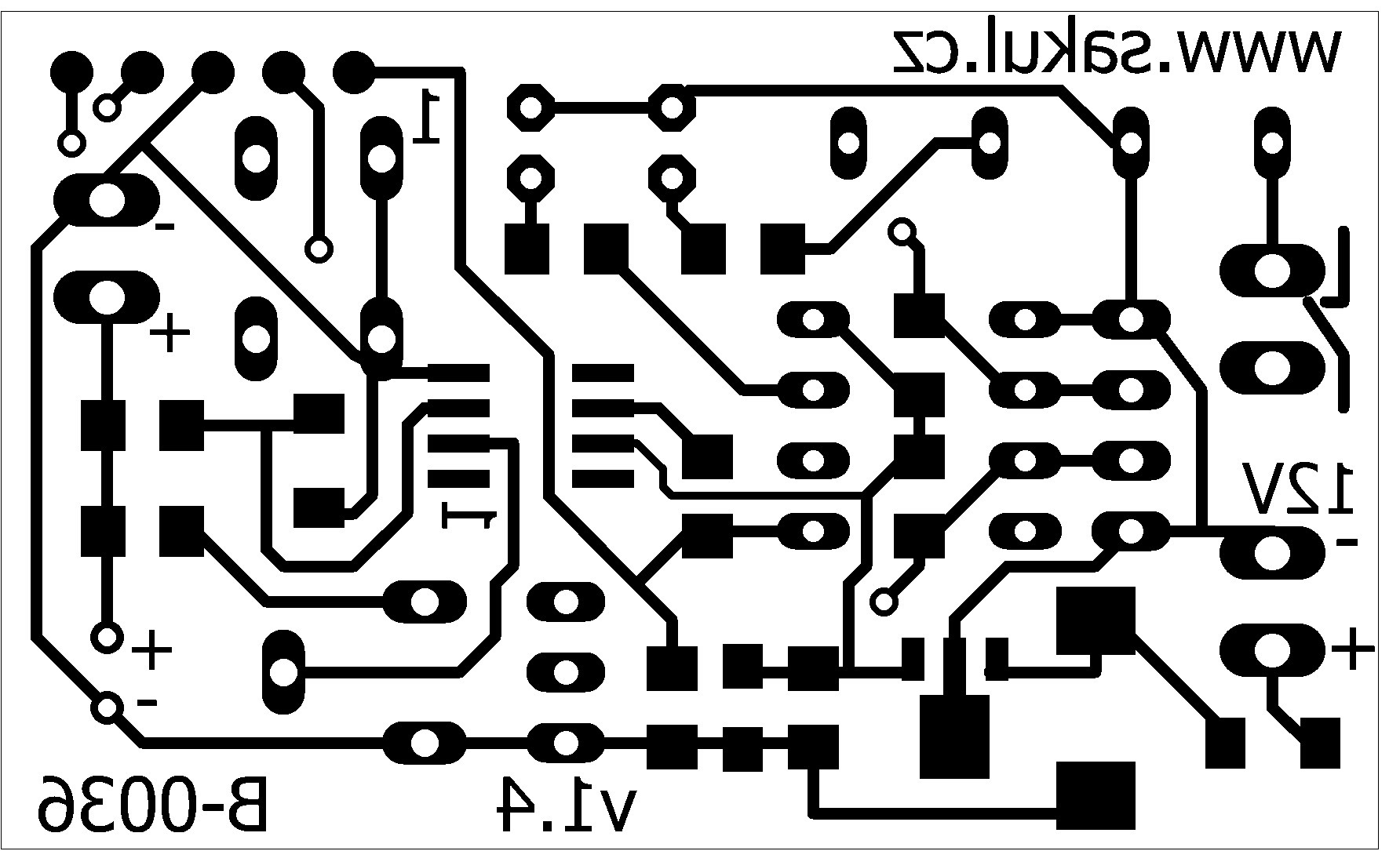
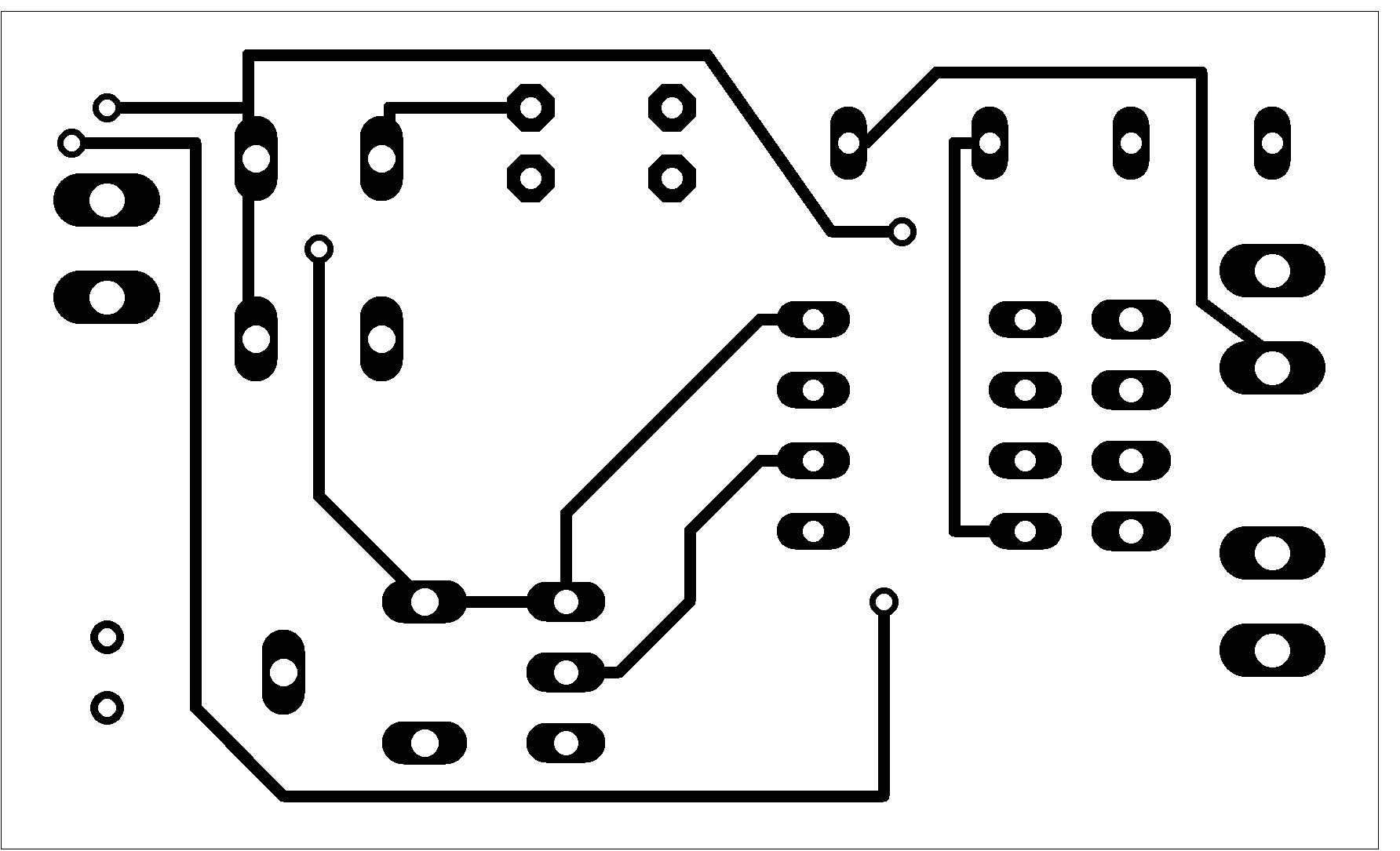
The PCB size is 50 x 30 mm. The first layer is BOTTOM and the second layer is TOP.
Assembly Plans
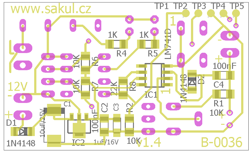
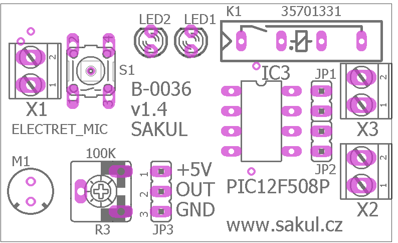
PCB and Assembly
The printed circuit board is double-sided with plated through holes. Most components are SMD so the board can remain compact. During assembly it is therefore necessary to work carefully; if the board does not have plated holes, vias must be made for example with thin wire soldered from both sides.
Sensitivity Setting
Sensitivity is adjusted with R3. The ideal setting allows the electronics to reliably detect the shot sound while avoiding false triggering from ambient noise. The microphone should be placed directly on the starting pistol and should be equipped with a pop filter, or otherwise protected so it does not react to wind gusts.
Function Description
After power-up the device performs a short initialization and internal check. If everything is correct, LED2 lights up and the device waits for a sound event. When the microphone detects sound of sufficient intensity, the processor evaluates it and generates a short pulse by switching relay K1. LED1 lights up and LED2 goes off. The microphone input is then blocked for about 15 seconds. After this time LED2 lights again and a new start can be performed.
If LED2 does not light within 10 seconds after power is connected, sensitivity must be adjusted with R3. In normal use the trimmer can usually be set near the middle of its travel. After adjustment, restart the device or wait 15 seconds. When connecting the microphone, observe correct polarity; reverse polarity may make the device non-functional and may damage the microphone or the electronics.
Connectors and Indicators
| Label | Description |
|---|---|
X1.1 | External microphone terminal, positive voltage. |
X1.2 | External microphone terminal, GND. |
X2.1 | Power input +8-15 V/DC. |
X2.2 | Power input GND. |
X3.1/2 | Relay switching contact for stopwatch start. |
JP1 | External button connection. |
JP2 | Currently unused. |
JP3 | Currently unused. |
TP1-TP5 | Programming pads, see schematic. |
LED1 | Relay active indication, yellow. |
LED2 | Ready indication, green. |
Documentation
The complete documentation package contains build files, the Eagle project and the microcontroller firmware.
Processor configuration:
__CONFIG _MCLRE_OFF & _CP_ON & _WDT_OFF & _IntRC_OSCNotice
This construction is original author work. Copying it to other websites or using it commercially is not permitted without the author's consent. Linking to this website and this construction is allowed. The author accepts no liability for the behaviour of the device or any damage caused by its use. The device is intended only for personal use. The construction contains microcontroller firmware protected by copyright; any sale is not possible without the author's consent.