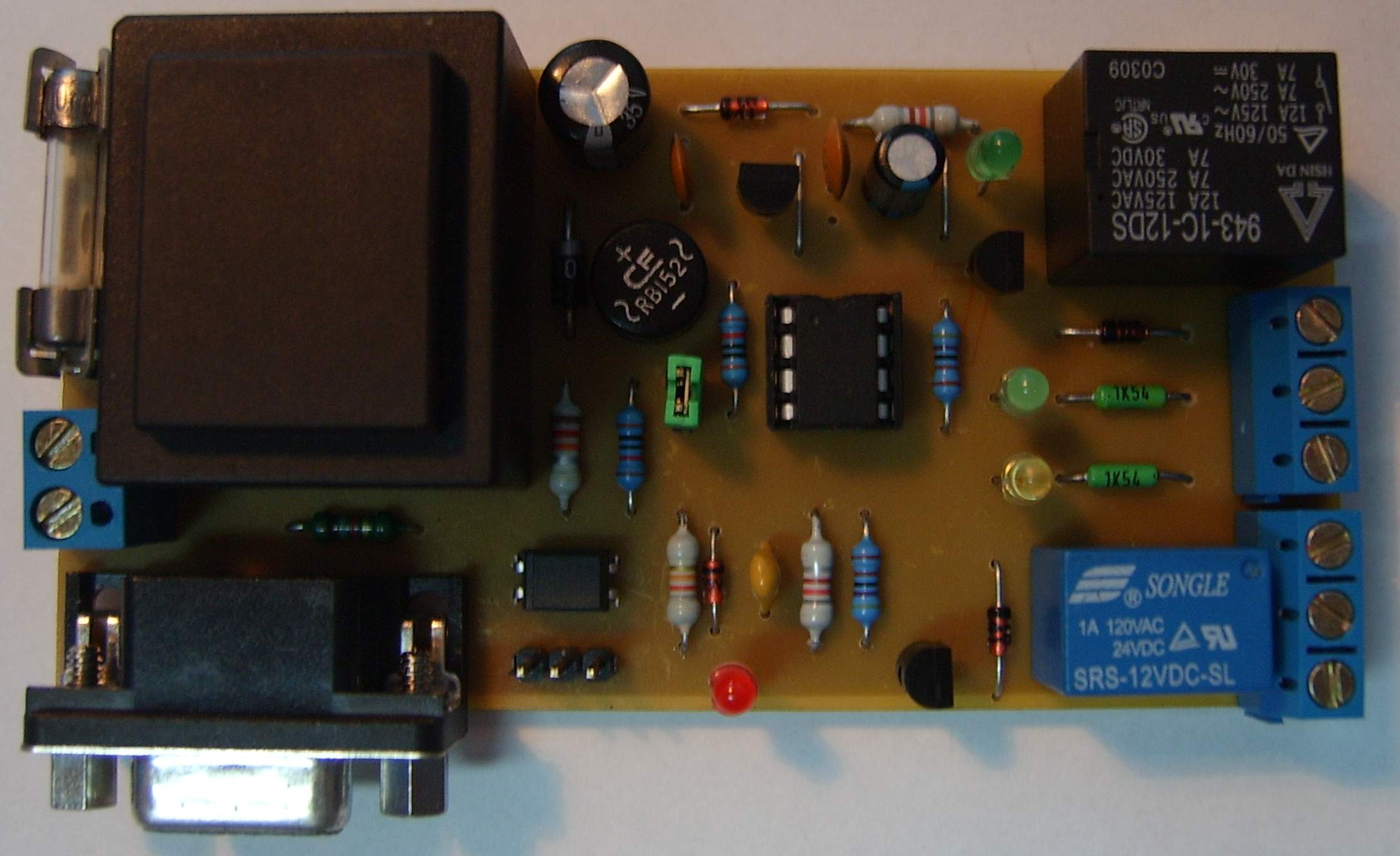
This device was created to start an older PC automatically after a power outage. Newer ATX motherboards can often be configured in BIOS to power up after power returns, but older boards do not always support this feature. The first version was built from discrete logic and three integrated circuits. This later microcontroller version is simpler and adds a watchdog reset mode.
What the Device Does
| 1 | After power is applied, it waits about one minute and monitors the mains voltage. If another dropout or voltage dip occurs, the startup delay is restarted until the mains supply is stable. |
|---|---|
| 2 | When the mains supply is stable, relay RE1 connects power to the PC or another device. About ten seconds later relay RE2 simulates the PC power button with a pulse shorter than one second. |
| 3 | The basic mode works as a starter. When jumper JP1 is fitted, the extended resetter mode is enabled and the device monitors external watchdog pulses. |
Resetter Mode
In resetter mode the device first starts the PC in the same way as in starter mode. A delay of about 1:20 minutes follows, allowing the PC to boot. The Watchdog v1.1 program running on the PC sends periodic pulses through the RS232 port. The microcontroller monitors these pulses.
If pulses arrive within the expected interval, the PC is considered healthy. Two microcontroller firmware variants are available: one expecting one-second pulses and one expecting one-minute pulses. If pulses stop arriving, the device disconnects the PC from power, waits for mains stability again, powers it back on and sends another power-button pulse. To avoid an endless restart loop, only three restarts are allowed. After that the pulses are ignored and the PC remains powered on, with the fault indicated by the red LED.
Hardware
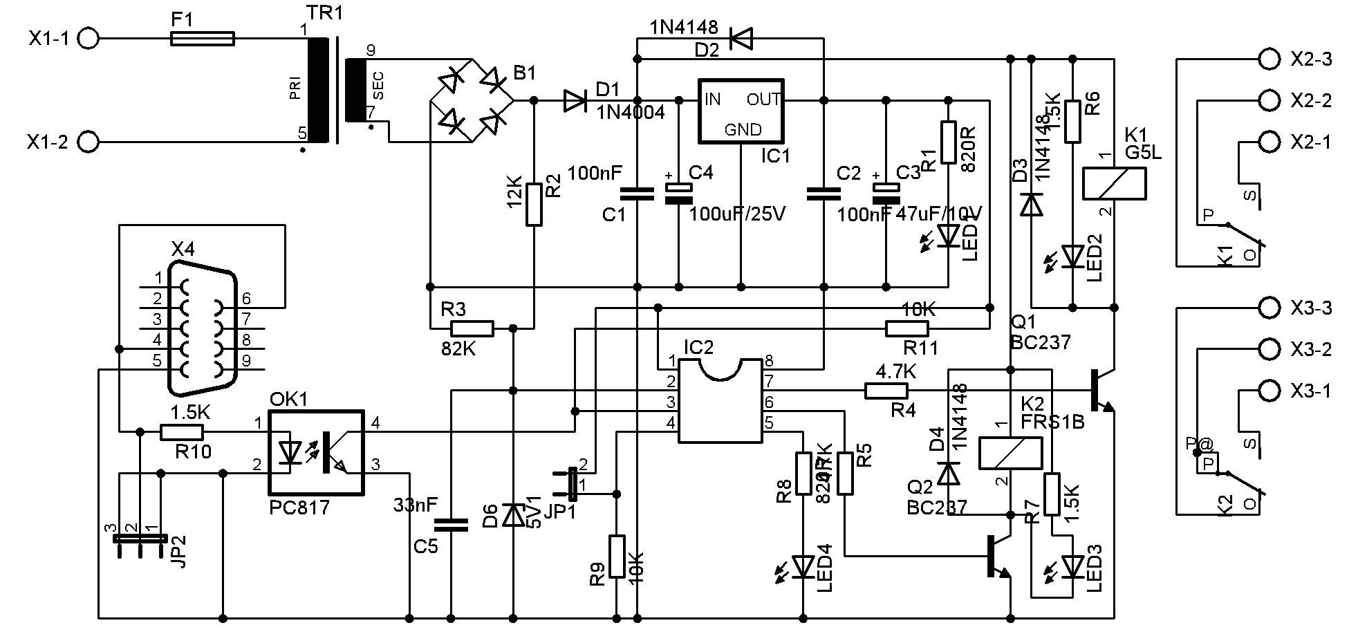
The device is built on a single-sided PCB with two wire jumpers. It is powered directly from 230 V AC through terminals X1. A 9 V / 1.9 VA transformer, bridge rectifier and 78L05 regulator supply the PIC12F508 microcontroller. Relay coils are 12 V types connected to the rectified supply. Mains dropout detection is implemented with a simple divider behind the bridge rectifier using R2 and R3, with C5 and Zener diode D5 protecting the microcontroller input.
JP1 selects the extended resetter mode and should be fitted only while the device is powered off. PC watchdog pulses are received through a CANON9F connector. Pulses from other devices can be connected to JP2. JP2 is a three-pin connector with both outer pins grounded and the centre pin used for the positive input, so reversing the connector cannot reverse the polarity. The input is optically isolated for maximum flexibility.
Operating and Fault States
| LED1 on | The device is powered. |
|---|---|
| LED4 flashing | The device is waiting one minute for the mains voltage to stabilise. |
| LED2 on | Relay RE1 is on and the connected device is powered. |
| LED3 | Power-button pulse through RE2, about one second. |
| LED2 on, LED4 flashing | Extended resetter mode: external pulses are arriving from the PC or another device. |
| LED2 and LED4 on | More than three restart attempts were made because external pulses did not arrive in time. |
Use Beyond PCs
The resetter mode can also monitor switches, routers, Wi-Fi access points and other devices that indicate normal operation by a blinking LED. If such a device freezes, the LED often stops changing state. Connecting this signal to JP2 and using the one-minute firmware variant allows the resetter to detect the fault and power-cycle the device.
Bill of Materials
| Designators | Qty | Value / type | Note |
|---|---|---|---|
R1, R8 | 2 | 820R | |
R2 | 1 | 12K | |
R3 | 1 | 82K | |
R4, R5 | 2 | 4.7K | |
R6, R7, R10 | 3 | 1.5K | |
R9, R11 | 2 | 10K | |
C1, C2 | 2 | 100nF | |
C3 | 1 | 47uF/10V | |
C4 | 1 | 100uF/25V | |
C5 | 1 | 22nF | |
D1 | 1 | 1N4001 to 1N4007 | |
D2, D3, D4 | 3 | 1N4148 | |
D5 | 1 | ZD5V1 | Zener diode. |
IC1 | 1 | 78L05 | Voltage regulator. |
IC2 | 1 | PIC12F508 | Programmed microcontroller. |
K1 | 1 | GL5L 12V | Relay. |
K2 | 1 | FRS1B 12V | Relay. |
TR1 | 1 | 1x9V / 1.9VA PCB transformer | |
PCB | 1 | Single-sided 100x50mm |
Schematic
PCB and Assembly
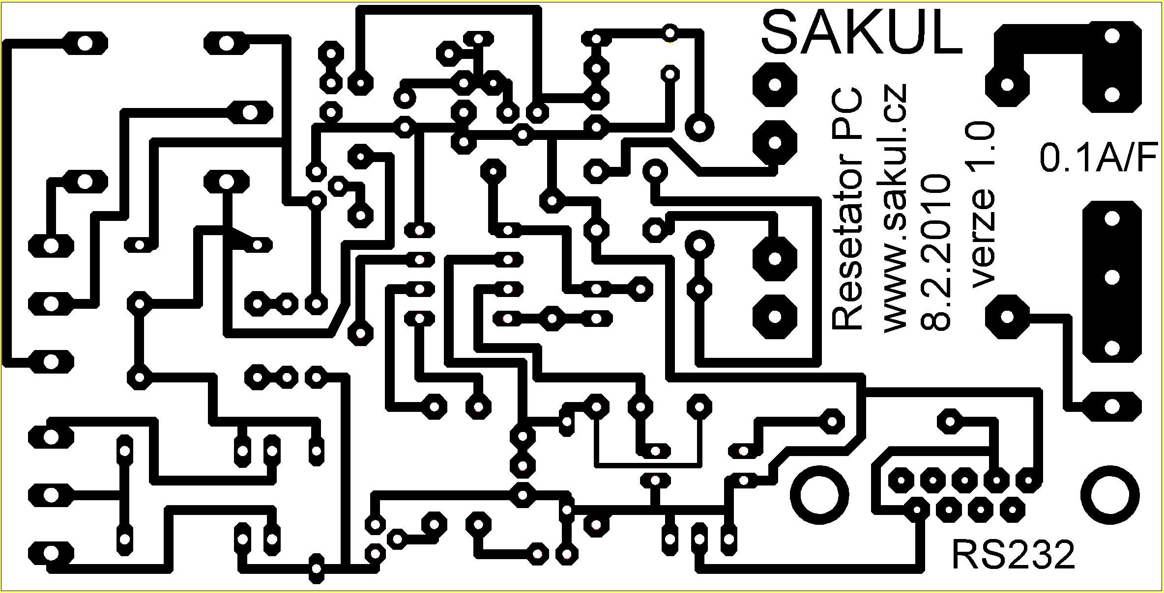
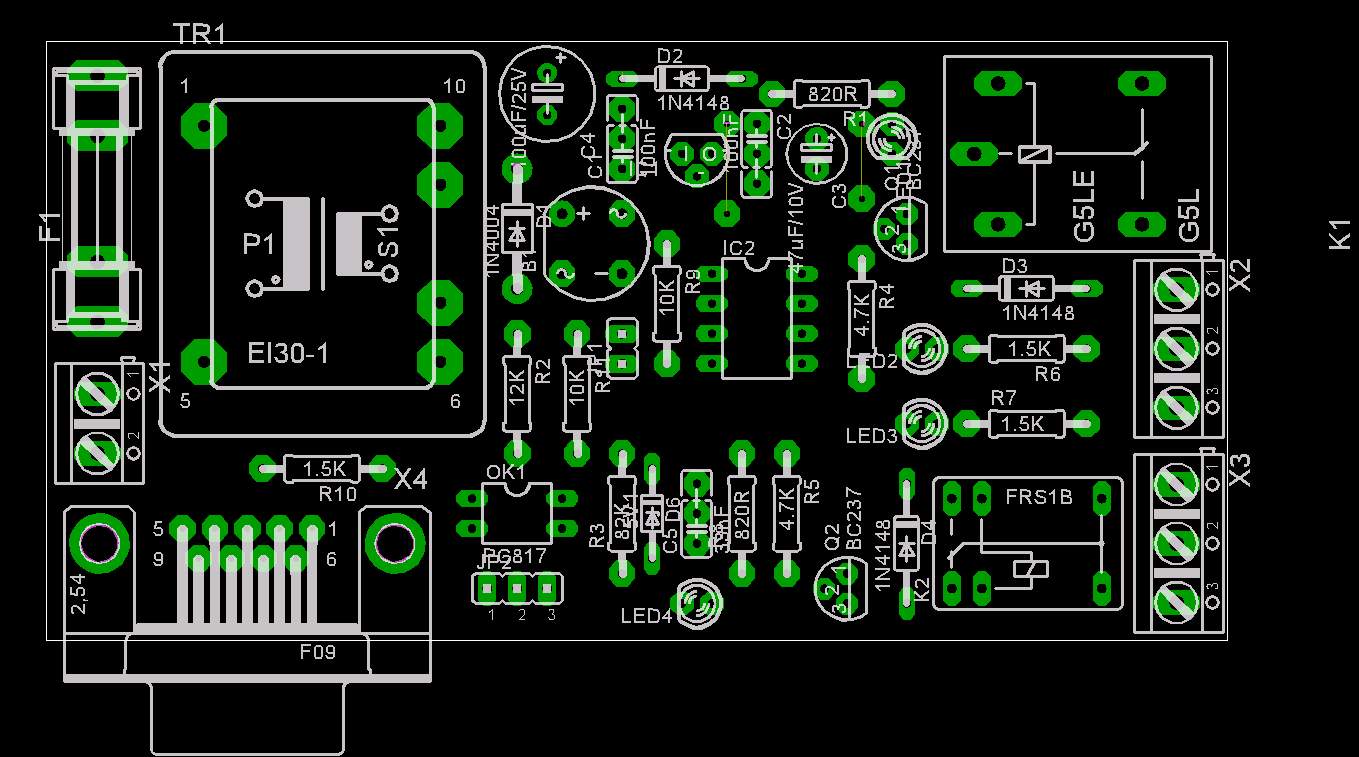
The PCB is a 100x50mm single-sided board. With careful assembly the device works on the first power-up and does not require adjustment. Do not forget the two wire jumpers.
Processor Configuration
| Item | Setting |
|---|---|
Oscillator | Internal oscillator. |
Watchdog | OFF. |
MCLRE | OFF. |
Code protection | As required. |
Documentation
The documentation archive contains construction files and firmware for the microcontroller. The Watchdog v1.1 PC program is available as a separate download.
Disclaimer
This is an author project intended for personal use. The author does not accept responsibility for device behaviour or any damage caused by its use. The Watchdog v1.1 program and microcontroller firmware are copyrighted and may be used free of charge for personal use only.