Project Sponsor
This project was sponsored by PCB manufacturer PCBWay.

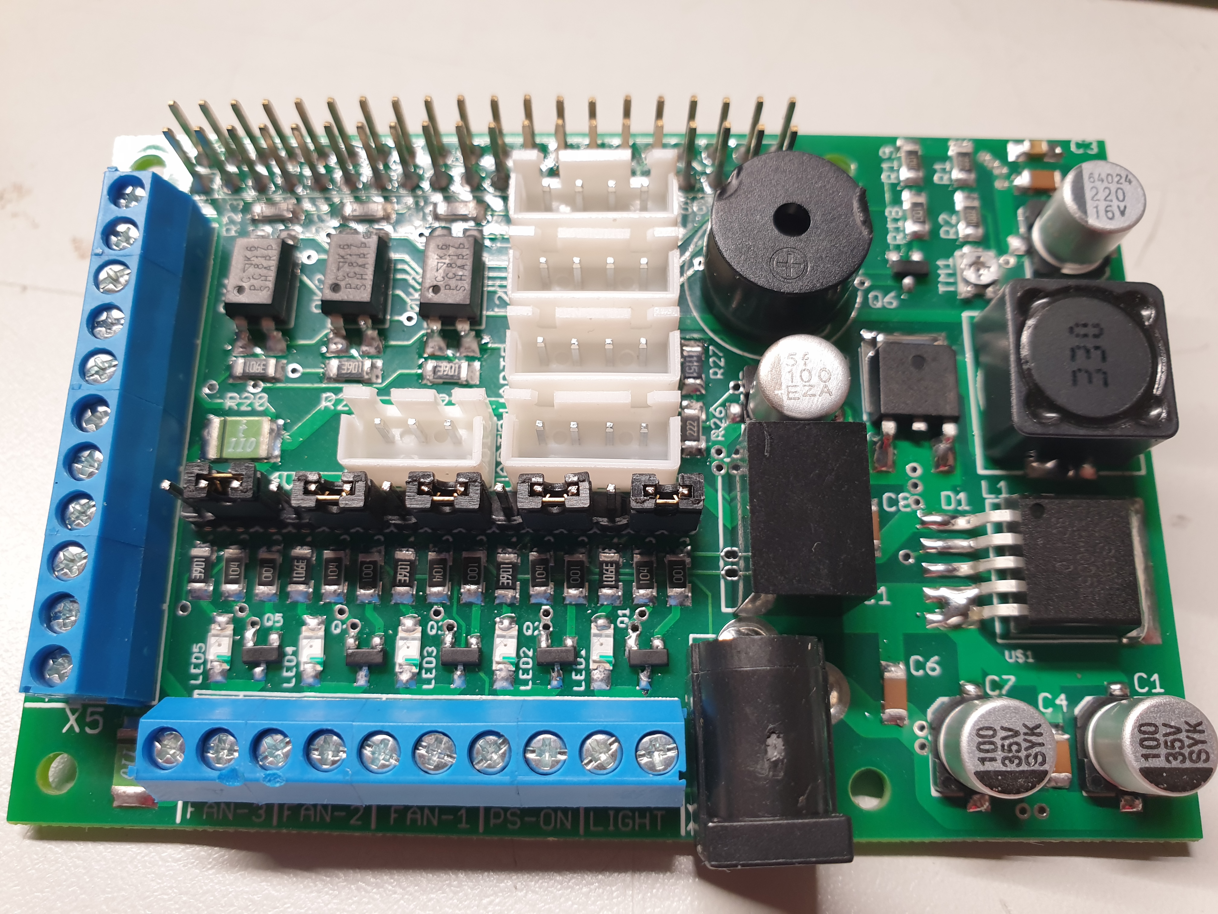
The RaspberryPi IO Shield expands Raspberry Pi GPIO for 3D printer server use. It adds protected inputs, power outputs, communication connectors and an onboard DC/DC converter so the whole print server can be powered directly from the printer supply.
Technical Specifications
| Supply | 8-30 V DC, 5.5 x 2.1 mm jack. |
|---|---|
| Inputs | 3 optically isolated inputs for sensors or endstops. |
| Outputs | 5 power outputs, up to 1 A each when using supply voltage output. |
| Output voltage | Selectable 12 V or input supply voltage, typically 24 V. |
| 5 V output | Protected 5 V / 1 A output, also usable for WS2812B LEDs. |
| Interfaces | 2x I2C, 2x UART, OneWire/universal IO and a pass-through 40-pin Raspberry Pi connector. |
| Supported boards | Raspberry Pi Zero W, Zero 2 W, 3, 3B, 3B+ and 4B. |
Schematic and Placement
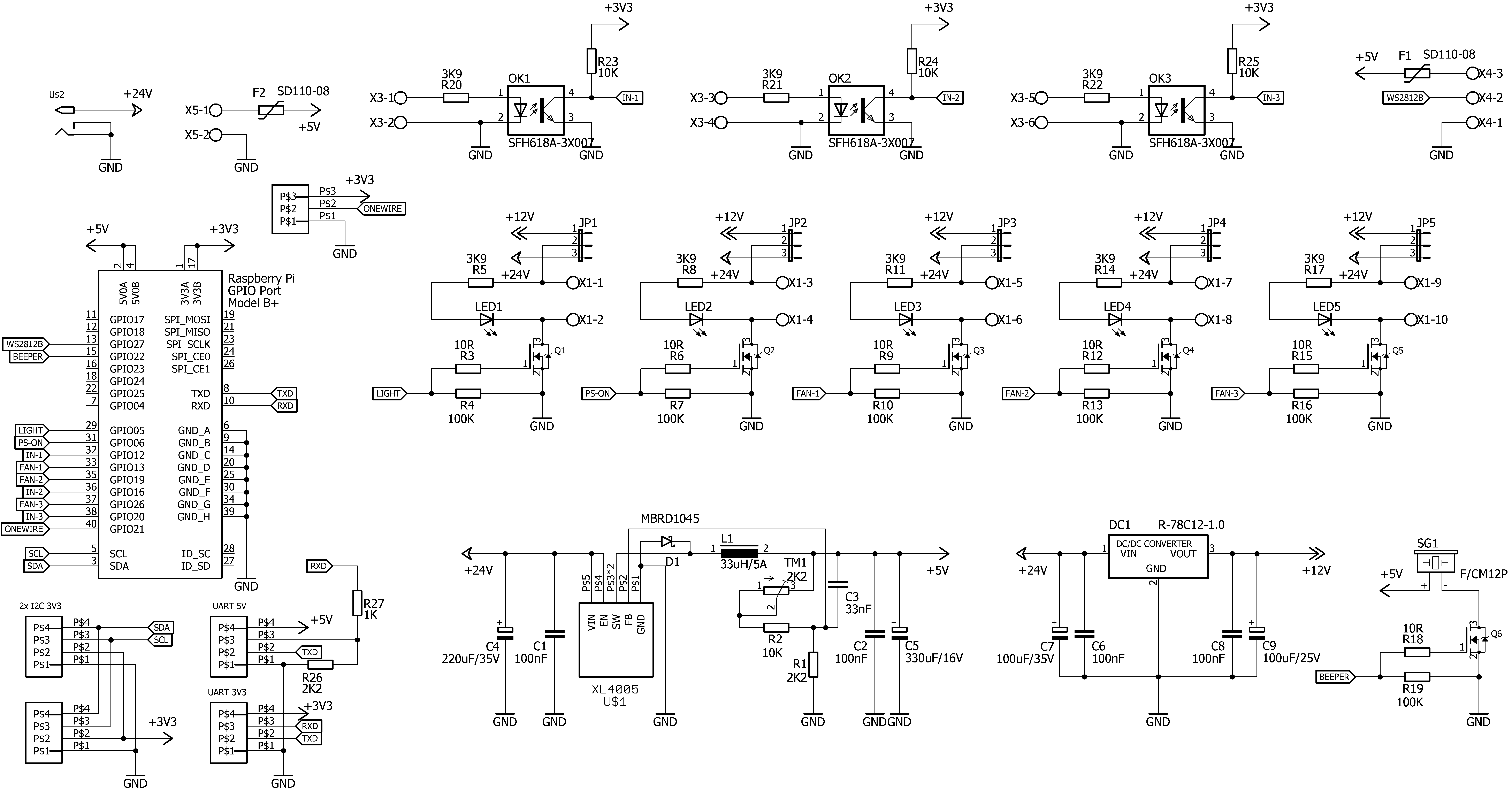
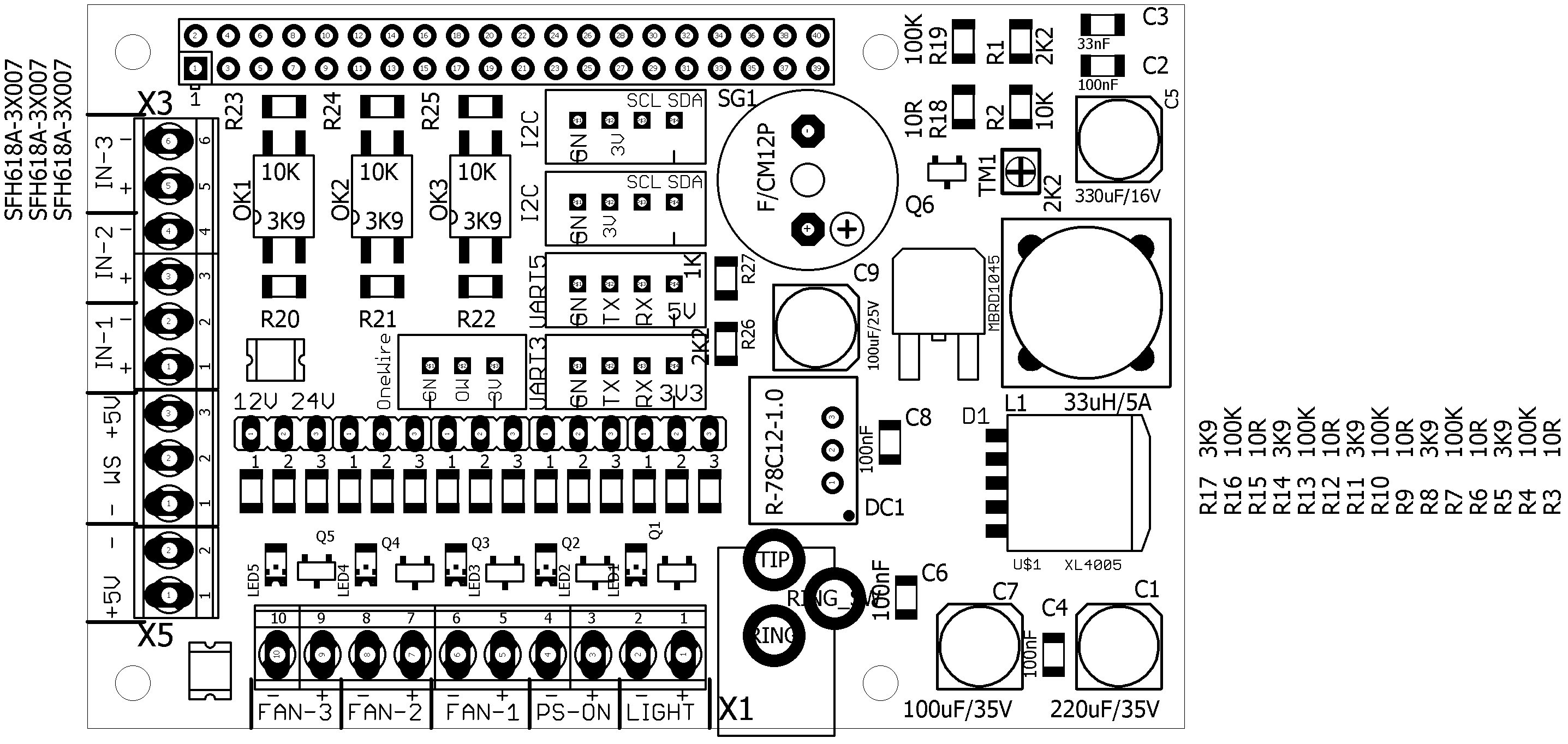
Bring-up
During bring-up, set the onboard DC/DC converter output to 5.1 V using trimmer TM1. The shield plugs directly into the Raspberry Pi 40-pin connector. M2.5 spacers are recommended to hold the board in position.
Klipper Integration
Klipper can use Raspberry Pi as an additional host MCU. After enabling the RPi microcontroller support, GPIO pins from this shield can be controlled from printer.cfg.
cd ~/klipper/
sudo cp "./scripts/klipper-mcu-start.sh" /etc/init.d/klipper_mcu
sudo update-rc.d klipper_mcu defaults
make menuconfig
sudo service klipper stop
make flash
sudo service klipper start
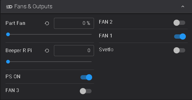
The optically isolated inputs use inverted logic. In Klipper configuration the input can be inverted by adding an exclamation mark before the pin name, for example switch_pin: !host:gpio12.
Documentation
The documentation package contains full project files, schematic details, bill of materials and configuration examples.
Notice
EA means Early Access. The construction is usable but may continue to evolve and may not include every final feature. The operator is responsible for using it safely.