Introduction
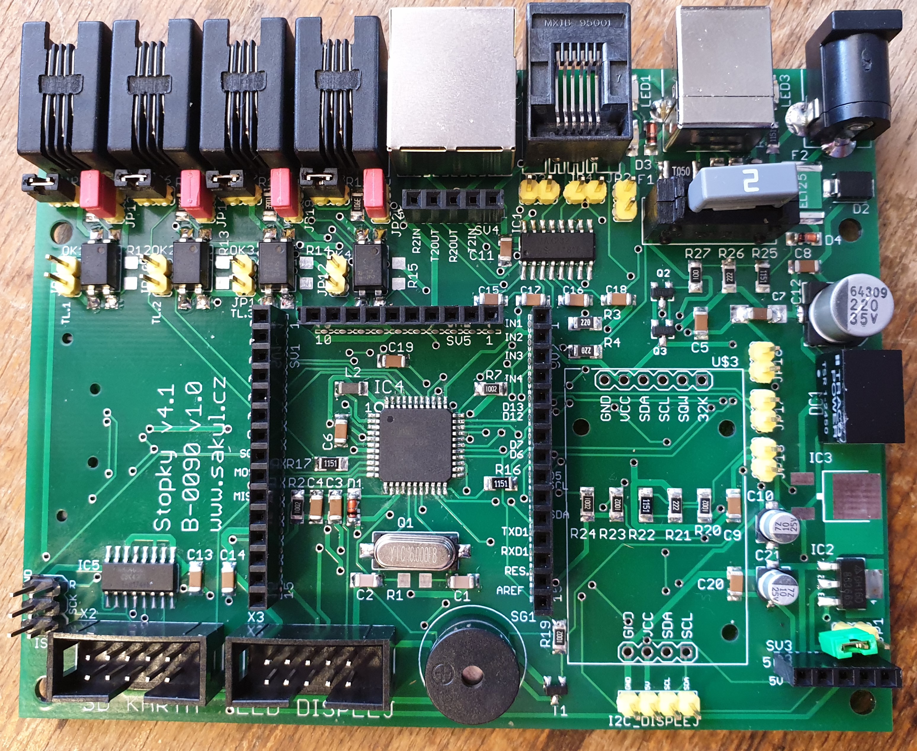
This version of the stopwatch is a more advanced construction intended not only for fire sport timing. It is based on the ATmega32U4 microcontroller and builds on long-term experience with custom stopwatch systems. The firmware can be adjusted to adapt the device to specific requirements.
Technical Parameters
| PCB | B-0090 |
|---|---|
| Supply voltage | 8-15 V DC, polarity matters, center pin is positive. |
| Internal current draw | Approximately 100 mA. |
| External current draw | Up to 1.5 A. |
| Internal fuse | 0.75 A resettable fuse. |
| External fuse | 2 A mini automotive fuse. |
| Internal LCD resolution | 59:59:999. |
| Internal LCD | Backlit 2x16 character LCD. |
| Internal LED display | Optional one-line seven-segment display, 59:59:99. |
| External display | Optional two-line LED strip display, 59:59:99. |
| Inputs | Optically isolated START, RESET, STOP-L and STOP-P. |
| Combined input | RJ45 containing START, STOP-L and STOP-P. |
| Diagnostics | Input configuration test according to the selected mode. |
| Operating modes | Three modes. |
| PC connection | USB, 9600 bps, limited functionality. |
| Measured time logging | To PC or SD card, not supported in the free version. |
Operating Modes
Fire attack mode measures two lanes or targets. The time for each lane is shown on a separate display line. After reset, the system starts a preparation countdown, usually five minutes. Once the countdown finishes, the stopwatch displays measured lane times on the internal LCD and on the external display. START can be triggered by button or by input IN1. STOP-L and STOP-P stop the left and right lane independently.
Start/Stop mode uses a single measured channel. The lower display line shows 00:00:000. The measurement is started by START or IN1. After start, IN1 is blocked for a configurable time to prevent accidental stopping caused by a faulty trigger mechanism. After this blocking time, the next START or IN1 event stops the measurement.
Separate Start/Stop mode is similar to Start/Stop mode, but start uses START or IN1 and stop uses STOP-L or STOP-P.
Controls
The stopwatch is controlled through rear-panel inputs or buttons on the enclosure lid. The available inputs are START (IN1), RESET (IN2), STOP-L (IN3) and STOP-P (IN4). Before measurement starts, the stopwatch checks whether STOP inputs are in the expected state. If a stop signal is already active, an error message is shown and the device waits until the fault is removed.
External Display
An external display with up to six digits in two rows can be connected to output J1. It shows values in the 59:59:99 format. Milliseconds are not shown on the external display because they are usually not necessary and would make the display more expensive. The stopwatch always sends all display data and the external display uses the digits that are actually populated.
Power Supply and PC Connection
The stopwatch can be powered from USB when connected to a PC, but for full operation an 8-12 V supply connected to US2 is recommended. The connector is a standard 5/2.1 mm DC jack with the center pin positive. If optical sensors such as laser gates are powered from the stopwatch inputs, a 12-15 V supply may be more suitable depending on the sensors used.
The stopwatch can send data to a PC over USB. A terminal application can log received data to a text file, which is useful because the stopwatch display shows only the current race data. This feature may not be supported by every firmware version.
Settings
The stopwatch can be configured manually with buttons and the internal LCD, or remotely from a PC using AT commands over USB.
| Operating mode | Default 1, range 1 to 3. |
|---|---|
| Countdown time | Default 5 minutes, used as team preparation time. |
| Blocking time | Default 5 seconds, used in Start/Stop mode. |
Manual setup is entered by holding START while connecting power. STOP-L increases the selected value, STOP-P decreases it and START moves to the next editable position. Leaving the setup mode stores the values.
AT-Rezim1* sets the operating mode.
AT-Blokovani5* sets the Start/Stop blocking time in seconds.
AT-Odecet500* sets the preparation countdown. For example 1530 means 15:30 and 500 means 5:00.
AT-Info* prints available stopwatch information to the terminal.
AT-Save* stores edited values to EEPROM.
Schematic
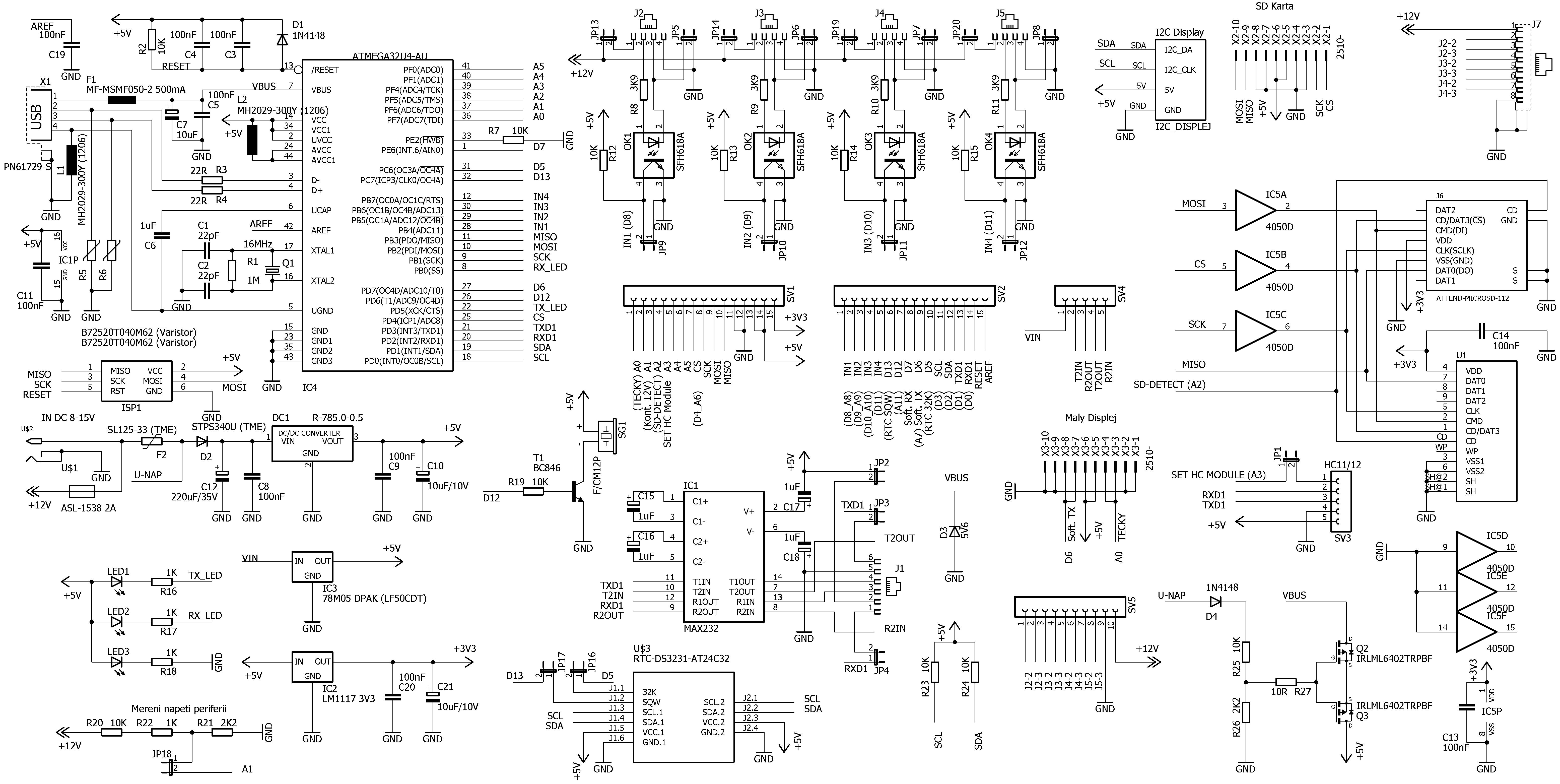
The schematic corresponds to a fully populated board. In practice not every part has to be populated; components are fitted according to the required functionality.
PCB Placement
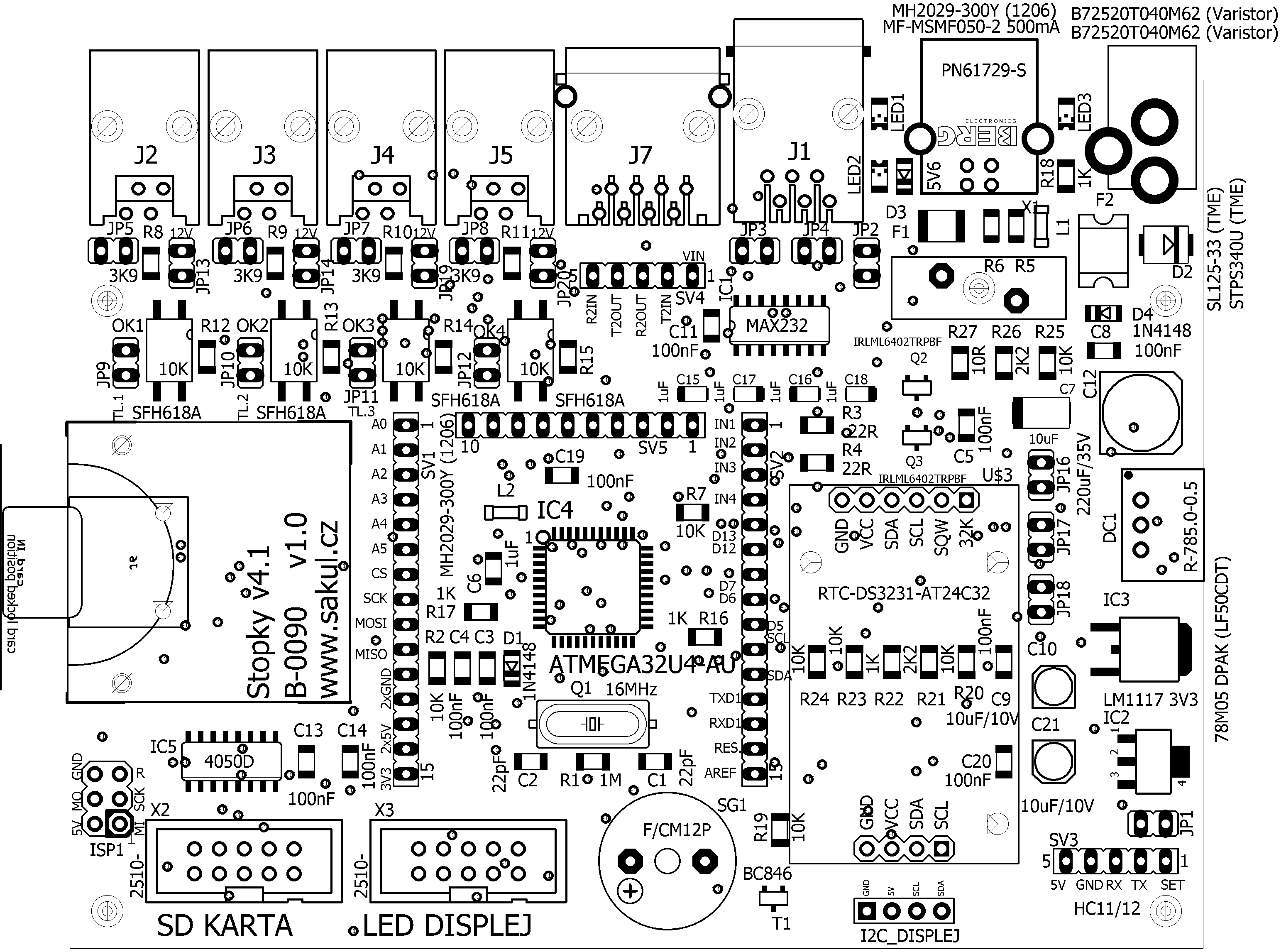
The stopwatch is built on a double-sided PCB.
Wireless Module Configuration
If wireless communication is used, for example with an external display, HC-11 or HC-12 modules can be used. The typical illustrative configuration is channel 4, FU3 mode and 19200 bps.
Firmware Update
The firmware can be updated over USB. The documentation package also includes the ArduinoBuilder.exe update utility, used with the board type set to Arduino Leonardo. A HEX firmware file is loaded and the update is started through the COM port assigned to the stopwatch.
The software site also provides related Sakul tools: Sakul Arduino Loader (SAL) for firmware work with supported projects and Sakul Serial Terminal (SST) for serial-port communication, connection testing and AT commands.
LCD Contrast
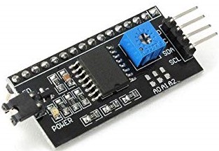
The LCD module uses an I2C converter on its underside. A small trimmer on the converter adjusts display contrast and a four-pin connector links the LCD module to the processor board.
Builder Notes
Some components on the board are not currently used because the corresponding functionality is not implemented in firmware. The construction is intended as a universal base for custom stopwatch systems, so only the parts required for the selected functionality need to be populated.
Only one of the 5 V regulators DC1 and IC3 must be populated. The choice depends on expected current draw and input voltage. DC1 is recommended when the internal LED display is used or when higher input voltage is expected. DC1 and IC3 must never be populated at the same time.
The stopwatch can use an alphanumeric 2x16 backlit LCD, optional internal seven-segment display and optional external display. Firmware support determines which display variants can be used.
Disclaimer
The author takes no responsibility for the behavior of the construction or for any damage caused by its use. All responsibility is assumed by the operator of the device. The construction is intended for personal use; commercial use or resale requires the author's permission.
Documentation and Support
The documentation package contains build files, schematic, PCB placement, processor firmware, firmware update utility and related materials.