The HC-05 is a very popular Bluetooth module that needs a 3.3 V supply for the module itself. It is commonly sold soldered to a small adapter board that is only slightly larger than the Bluetooth module. The adapter board usually contains a voltage regulator, status LED and a few resistors and diodes used for level adaptation, so the module can be connected to devices using 5 V logic, such as Arduino boards and similar platforms.
These modules can also be used to create a Bluetooth bridge between two devices, for example between two Arduino boards. This is where the HC-05 differs from the HC-06 module. The HC-05 supports both MASTER and SLAVE modes, which is the basic requirement for connecting two Bluetooth modules together. The following text focuses mainly on HC-05 modules mounted on an adapter board.
Technical Specifications
| Supply voltage | 3.6 to 6 V on the adapter board |
|---|---|
| Current draw | 30 to 40 mA, about 10 mA after pairing |
| Communication | UART, RX and TX lines |
| Supported baud rates | 4800 to 1382400 bps |
| Output power | Class 2, roughly 4 dBm / 2.5 mW |
| Range | about 10 m |
| Configuration | AT commands |
| Operating mode | Master / Slave |
| Bluetooth specification | v2.0 + EDR |
Use
The HC-05 module is universal. It can connect your application to a PC or mobile phone in SLAVE mode. It is also possible to set one module as MASTER and another one as SLAVE and connect them together, for example to link two Arduino boards or two embedded applications. In MASTER mode the module can also connect to devices such as a Bluetooth GPS. There are many possible combinations.
Connecting the Module
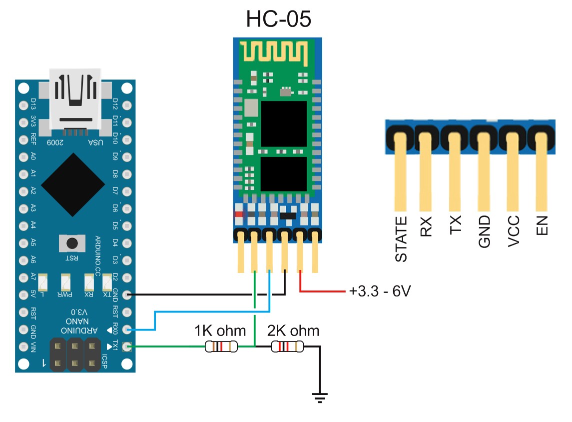
The picture shows a connection to an Arduino NANO board, but the module is connected in the same way to any other application that has a UART output with TX and RX data lines. The data lines between the Bluetooth module and the application must be crossed, as shown in the picture.
The TX line from the Arduino includes a resistor divider, shown as 1 kΩ (680 Ω) and 2 kΩ (1 kΩ). In many cases this divider may not be necessary, but with Arduino boards where the Bluetooth module is connected to a UART shared with a USB converter, it is recommended. Without the divider, data transfer errors may occur.
Configuration
The module is configured with AT commands. There are two ways to enter configuration mode. Each HC-05 module exposes one pin usually marked as KEY, EN or WakeUP. Applying 3.3 V to this input switches the module into configuration mode.
Method 1 – The KEY input is activated at the same time as power is applied to the module. The module enters configuration mode until it is restarted. In this mode the UART speed is fixed at 38400 bps. This method is recommended for one-time configuration.
Method 2 – The module is already running and the KEY input is activated afterwards. The module enters configuration mode without changing the UART speed. The speed remains the same as in normal operation.
The module can be configured only through the UART interface. It cannot be configured wirelessly from the computer. A USB/TTL converter must be connected to the module through TX and RX data lines. These lines must also be crossed.
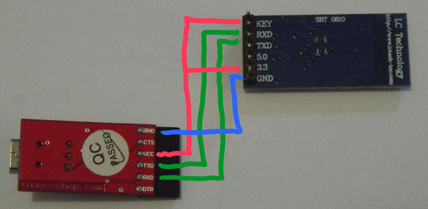
After connecting the Bluetooth module to the USB/TTL converter and the converter to the PC, a serial terminal is needed for sending AT commands. There are many serial terminals available. SimpleSerialTerminal is convenient for demonstrations because it is simple, clear and can store up to six predefined commands.
After the converter is connected to the PC, check which COM port was assigned to it. On Windows this can be found in Device Manager under Ports (COM and LPT).
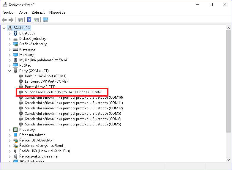
The example uses COM port 4, but the number can be different on every system. Set this port in the serial terminal and set the baud rate to 38400 bps when using the first configuration method. Then open the port and start sending AT commands.
To verify the connection, send the command AT. The module should respond with OK. Configuration mode can also be recognized by the slow LED blinking, roughly once every two seconds.
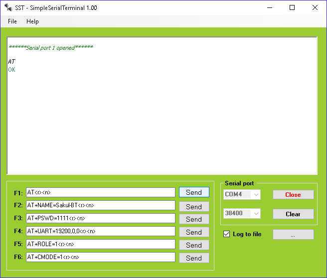
AT commands must be terminated with CR and LF characters. CR means Carriage Return and LF means Line Feed. If a different terminal is used, make sure it automatically appends these characters, or enter them manually.
Important AT Commands
This is not a complete list of all supported AT commands. It focuses on the most important commands needed for basic configuration.
AT+UART=<baud>,<stop>,<parity> changes UART settings. Supported speeds include 4800, 9600, 19200, 38400, 57600, 115200, 23400, 460800, 921600 and 1382400 bps. Stop bits use value 0 for 1 stop bit and 1 for 2 stop bits. Parity uses 0 for none, 1 for odd and 2 for even parity. Example: AT+UART=19200,0,0.
AT+UART? reads the current UART configuration. The question mark can be used with other commands in the same way to read the current value.
AT+NAME=<name> sets the Bluetooth module name. Example: AT+NAME=Sakul-BT. The new name is applied after the module is restarted.
AT+PSWD=<pin> sets the pairing PIN. The PIN is a four-digit number. The default PIN is 1234. Example: AT+PSWD=1111. The PIN is applied immediately.
AT+ROLE=<mode> selects SLAVE (0), MASTER (1) or SLAVE-LOOP (2) mode. Example AT+ROLE=1 sets MASTER mode.
AT+CMODE=<mode> sets pairing behavior and applies only when the module is in MASTER mode. Value 0 allows pairing only with a specific device defined by AT+BIND. Value 1 allows pairing with any SLAVE device if the PIN matches. Value 2 is used for SLAVE-LOOP devices. Example: AT+CMODE=1.
AT+BIND=<address> defines a specific device for pairing by MAC address. If the device address is 00:18:96:D1:48:D7, it can be written as AT+BIND=0018,96,d148d7. For many applications PIN-based pairing is sufficient, but the final security choice depends on the application.
AT+INIT initializes SPP records.
Conclusion
The HC-05 module is suitable not only for connecting an application to a PC or mobile phone, but also for connecting two Bluetooth modules together. One HC-05 can be used in MASTER mode and another HC-05 or HC-06 module can be used in SLAVE mode.
The module is also available as a bare module without an adapter board. This version is useful for direct integration into your own application. However, the maximum supply voltage must not exceed 4 V and the recommended range is roughly 3 to 3.7 V. The UART logic is also 3.3 V, so signals must be level-shifted when communicating with 5 V processors.
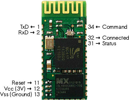
For experiments and prototypes it is usually more convenient to use the adapter-board version with an onboard regulator and easy-to-use connectors. The main drawback is the relatively short range of about 10 m, which should be considered when designing the application.
Documentation
A documentation package for the HC-05 module is available for download.