This construction was designed as a universal large display for the fire-brigade stopwatch. The goal was to keep it compatible with existing and future stopwatch versions without modifying the stopwatch itself. The same principle can also be used with other devices that drive multiplexed seven-segment LED displays, such as clocks, thermometers or similar units.
The display consists of several modules. The main part is a processor-controlled seven-segment digit connected to a serial bus. One digit contains 116 pieces of 5 mm LEDs. By combining multiple modules, a complete display with up to fifteen seven-segment digits can be built.
Each digit has a four-position DIP switch for its address. For the stopwatch display, the following addresses are used:
| Address | DIP | Meaning |
|---|---|---|
0 | 0000 | Colon. |
1 | 1000 | First digit, hundredths. |
2 | 0100 | Second digit, tenths. |
3 | 1100 | Third digit, seconds. |
4 | 0010 | Fourth digit, tens of seconds. |
5 | 1010 | Fifth digit, minutes. |
6 | 0110 | Sixth digit, tens of minutes. |
10 | 0101 | Seventh digit, target indication. |
Address 0 is fixed and controls the colon. Addresses 1 to 6 are the time digits. Address 10 shows additional target information: P for the right target, L for the left target and U for a finished measurement ready for a new run.
Seven-Segment Module
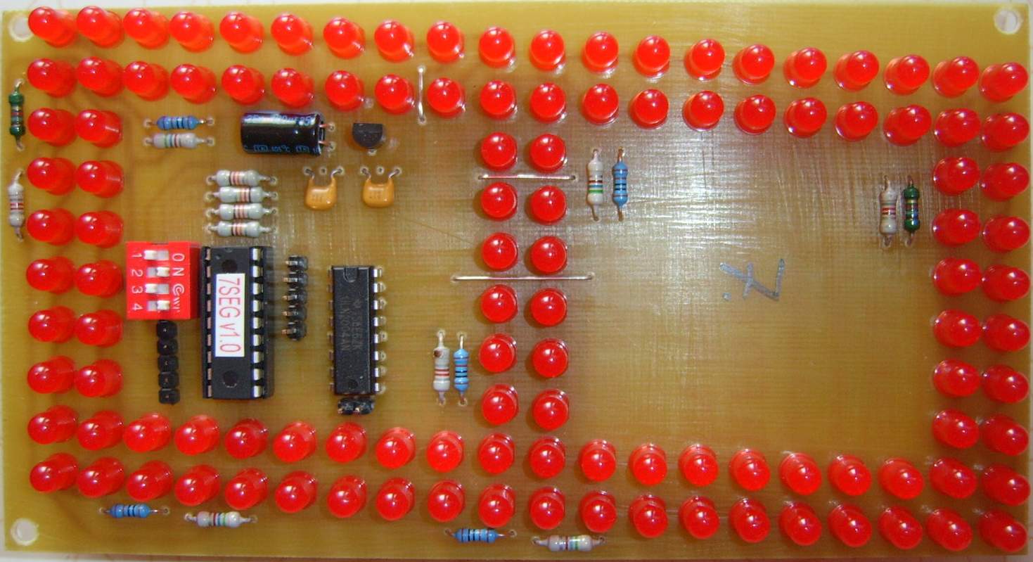
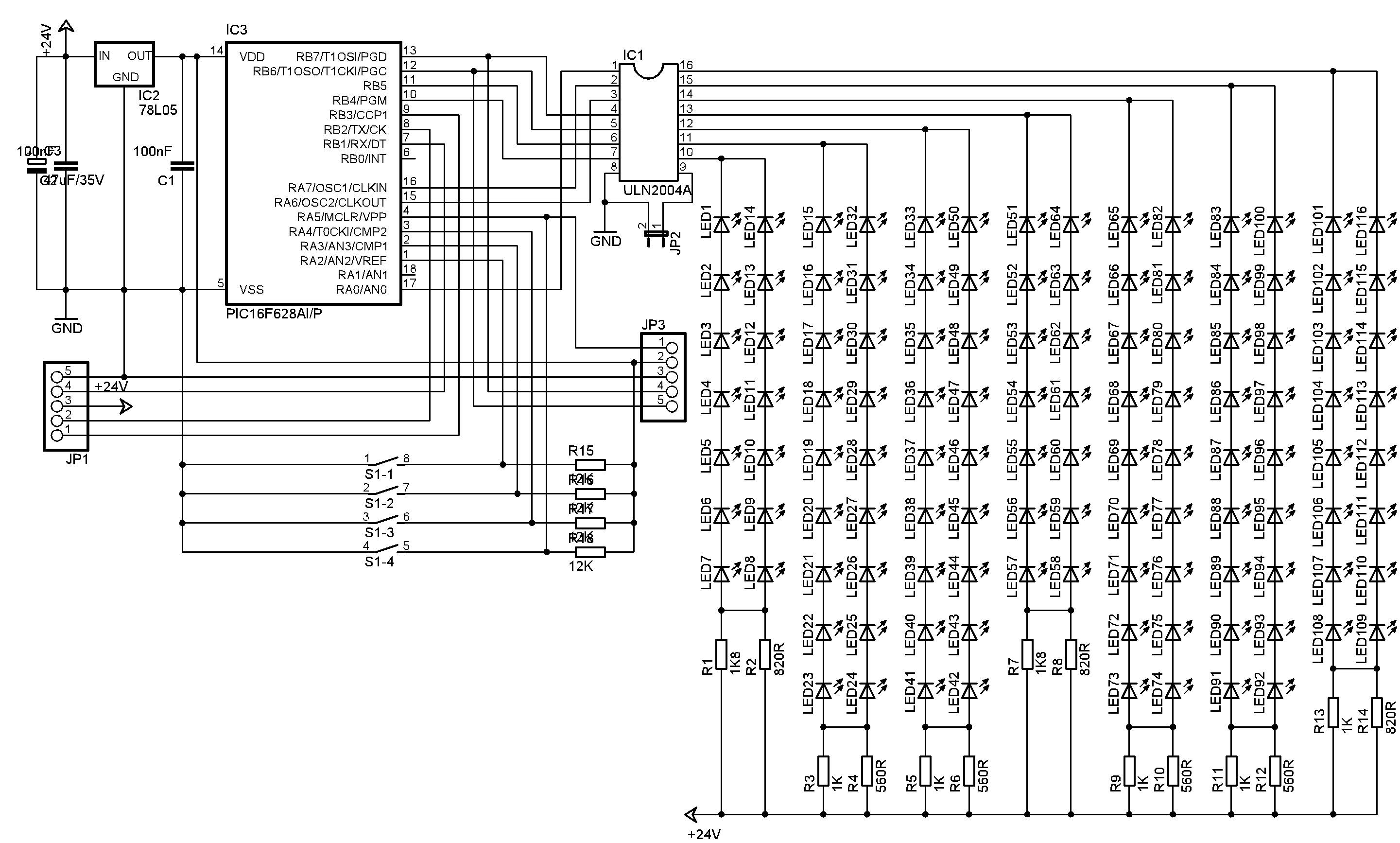
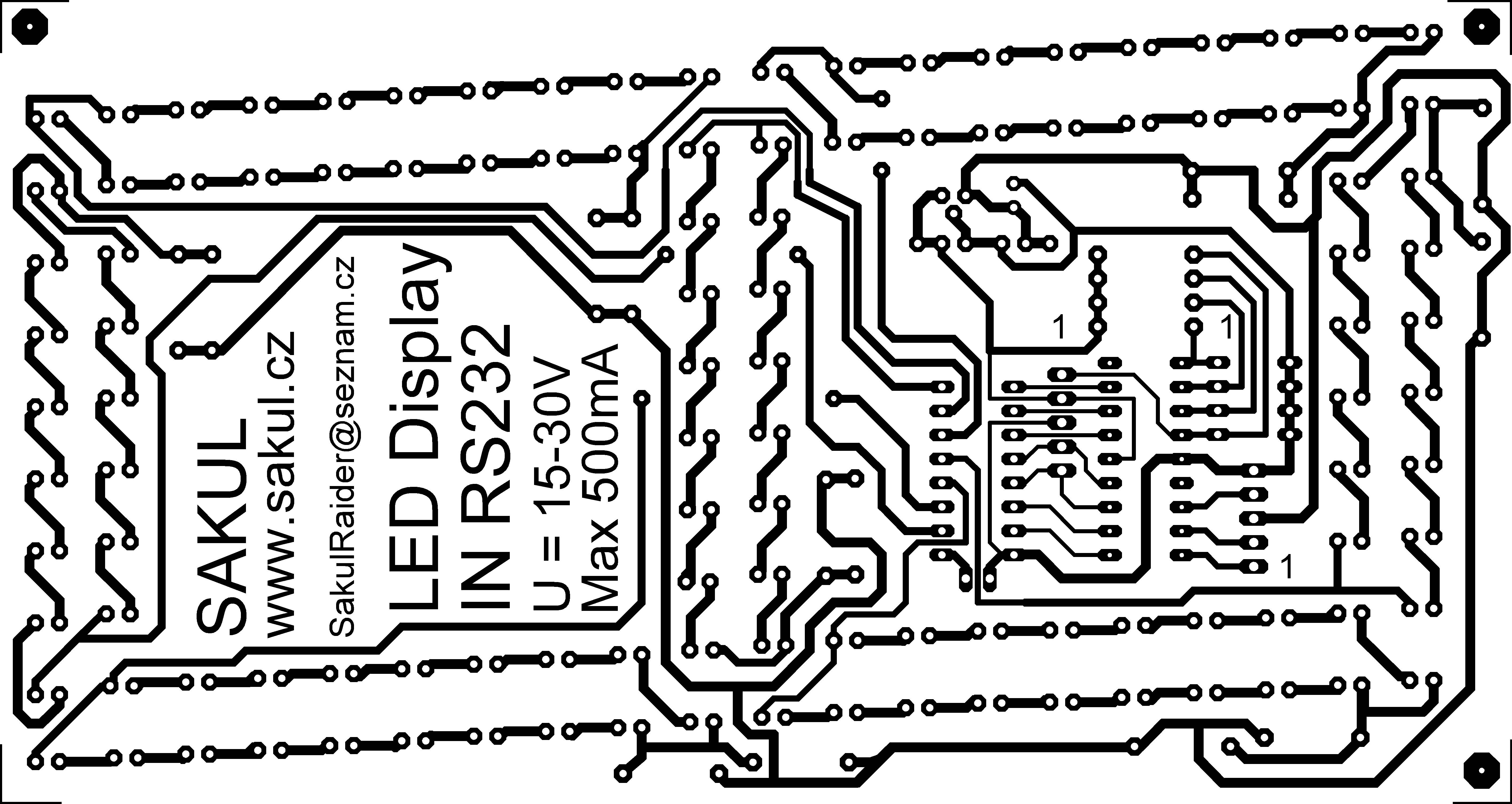
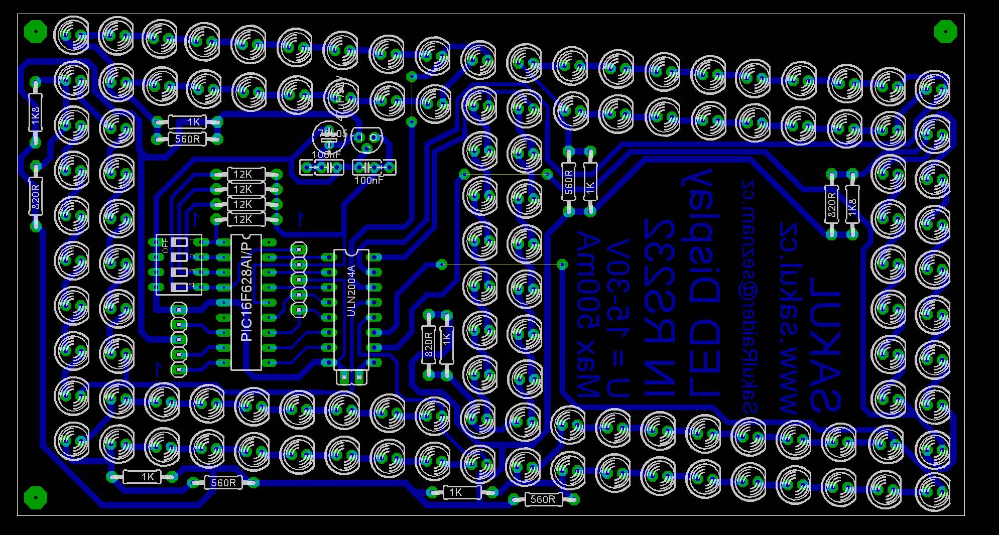
The module contains 116 LEDs arranged into individual segments. Each segment uses current-limiting resistors selected for the supply voltage and required brightness. Segment switching is handled by an ULN2004 driver. Jumper JP2 can enable all segments for testing. Display control and incoming data decoding is handled by a PIC16F628A microcontroller.
| JP1 pin | Meaning |
|---|---|
1 | Not used, connected to processor port RB3. |
2 | Not used, connected to the processor TX channel. |
3 | +24 V supply. |
4 | RX channel for incoming bus data. |
5 | GND. |
Power Module
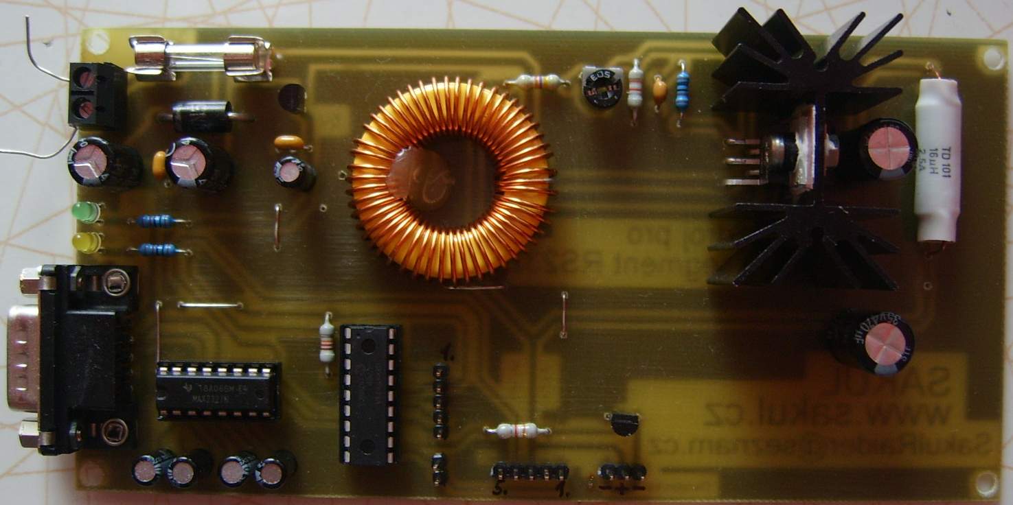
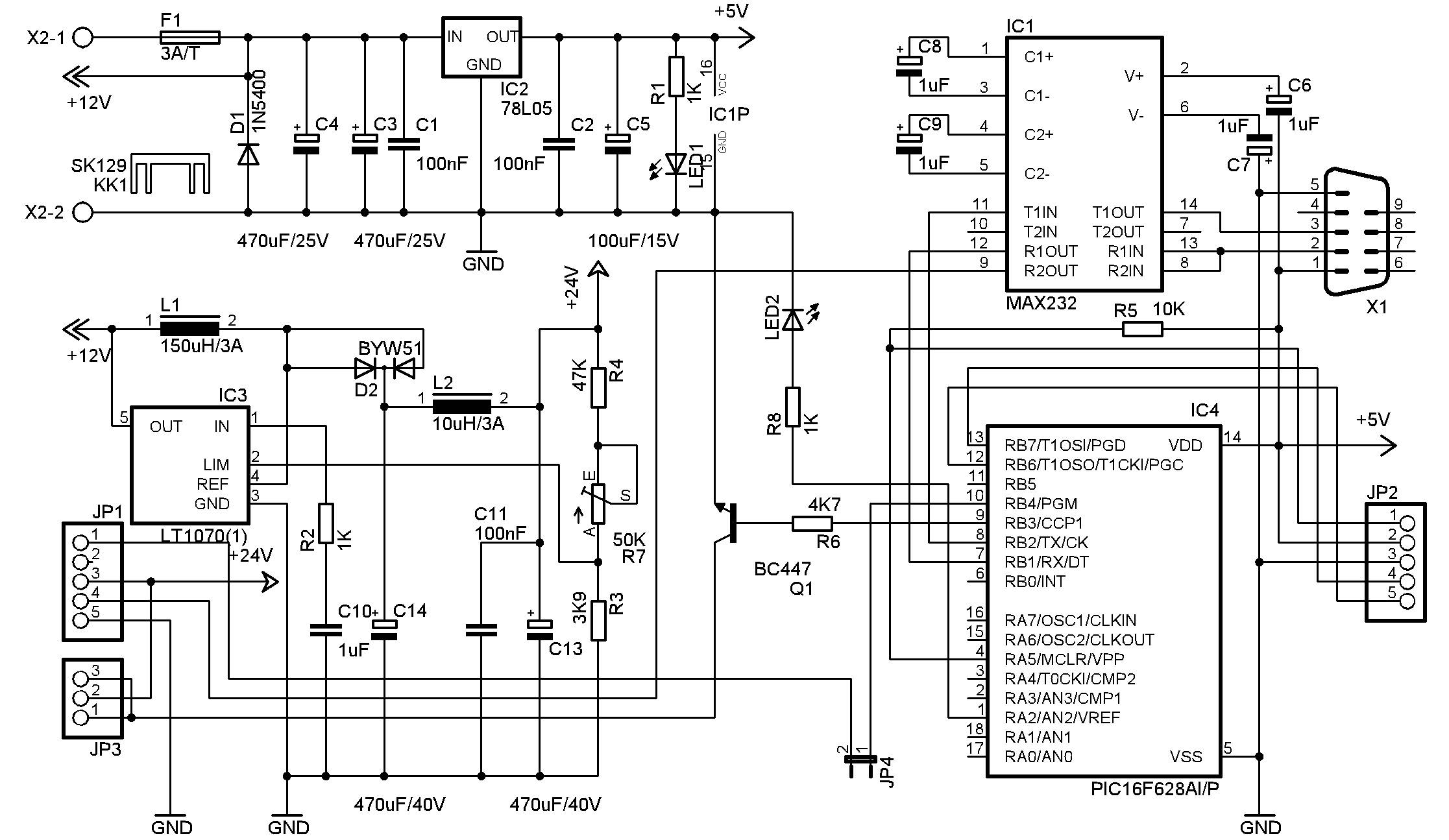
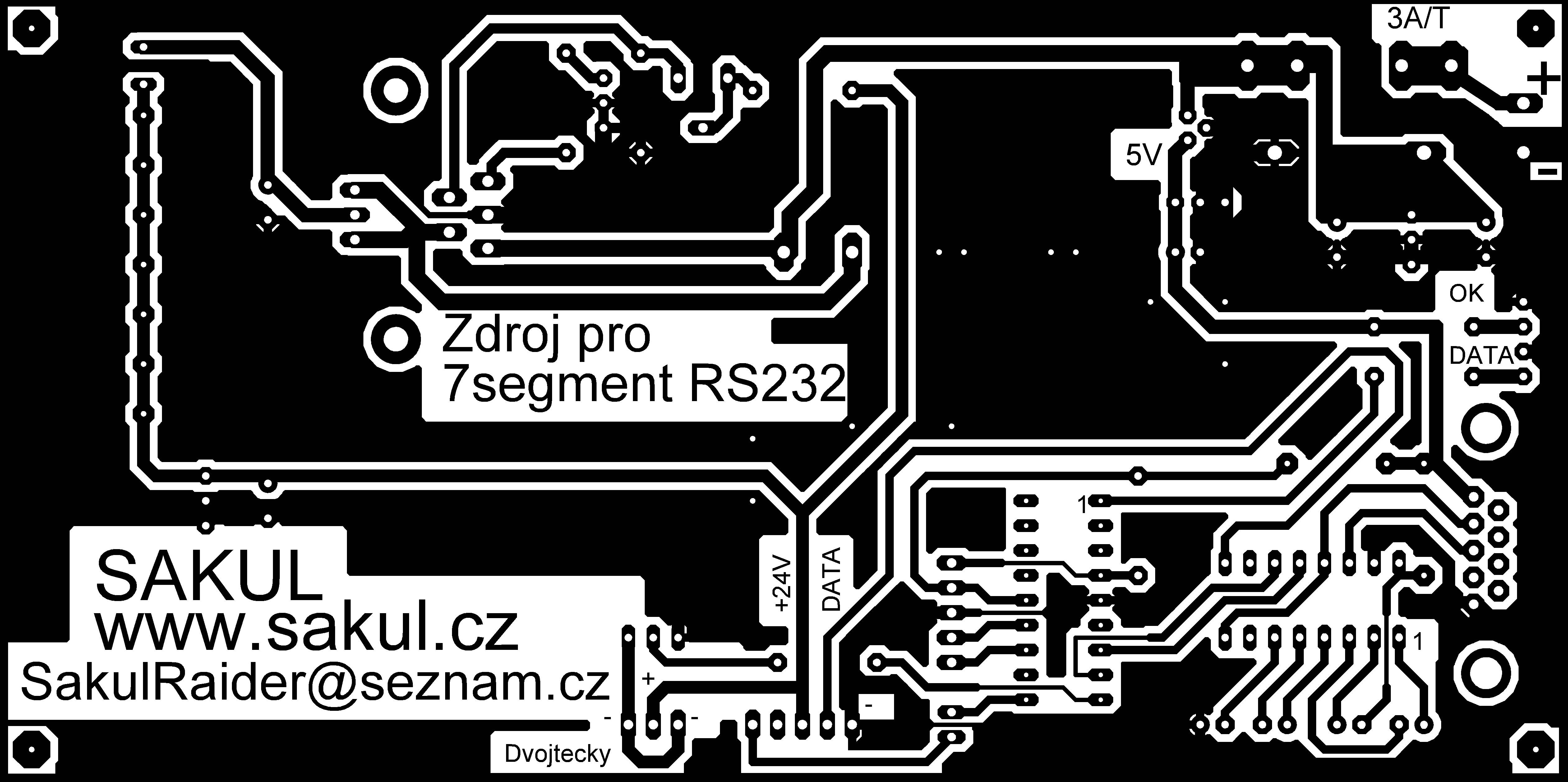
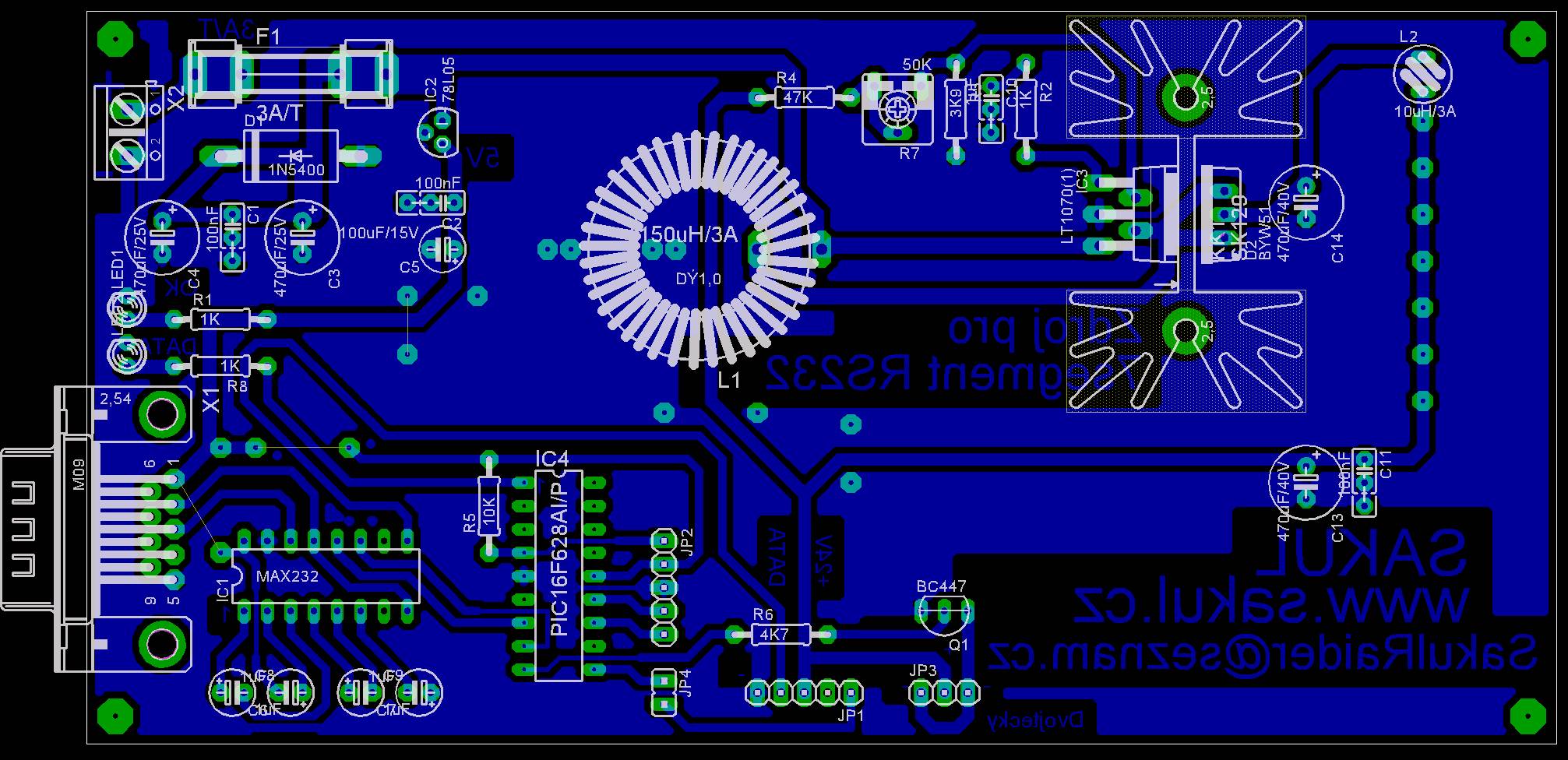
The power module is based on an LT1070 STEP-UP converter that generates approximately 24 V from a 12 V supply. The output voltage is adjustable by trimmer R7 from about 15 V to 30 V, which sets the display brightness. The module also contains a MAX232 RS232 converter, a PIC16F628A for colon control, a 78L05 regulator, input fuse, reverse-polarity protection and power indication.
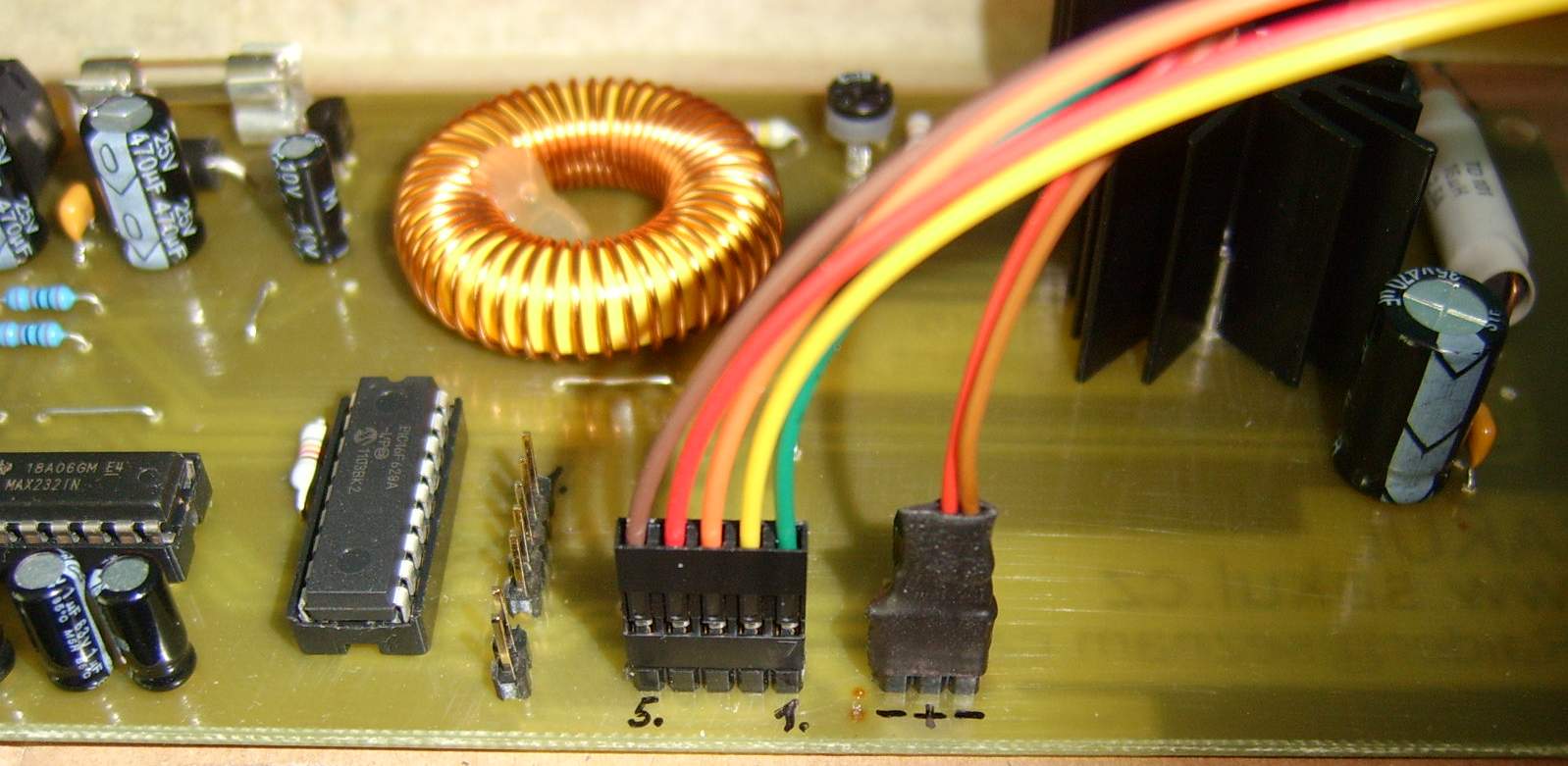
Converter Module
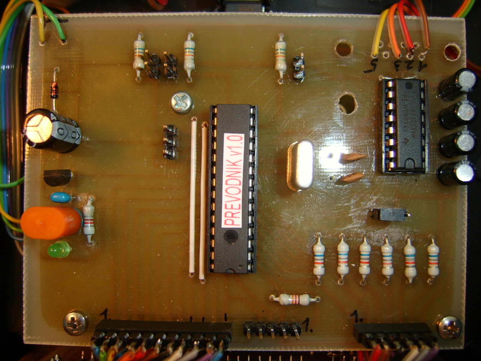
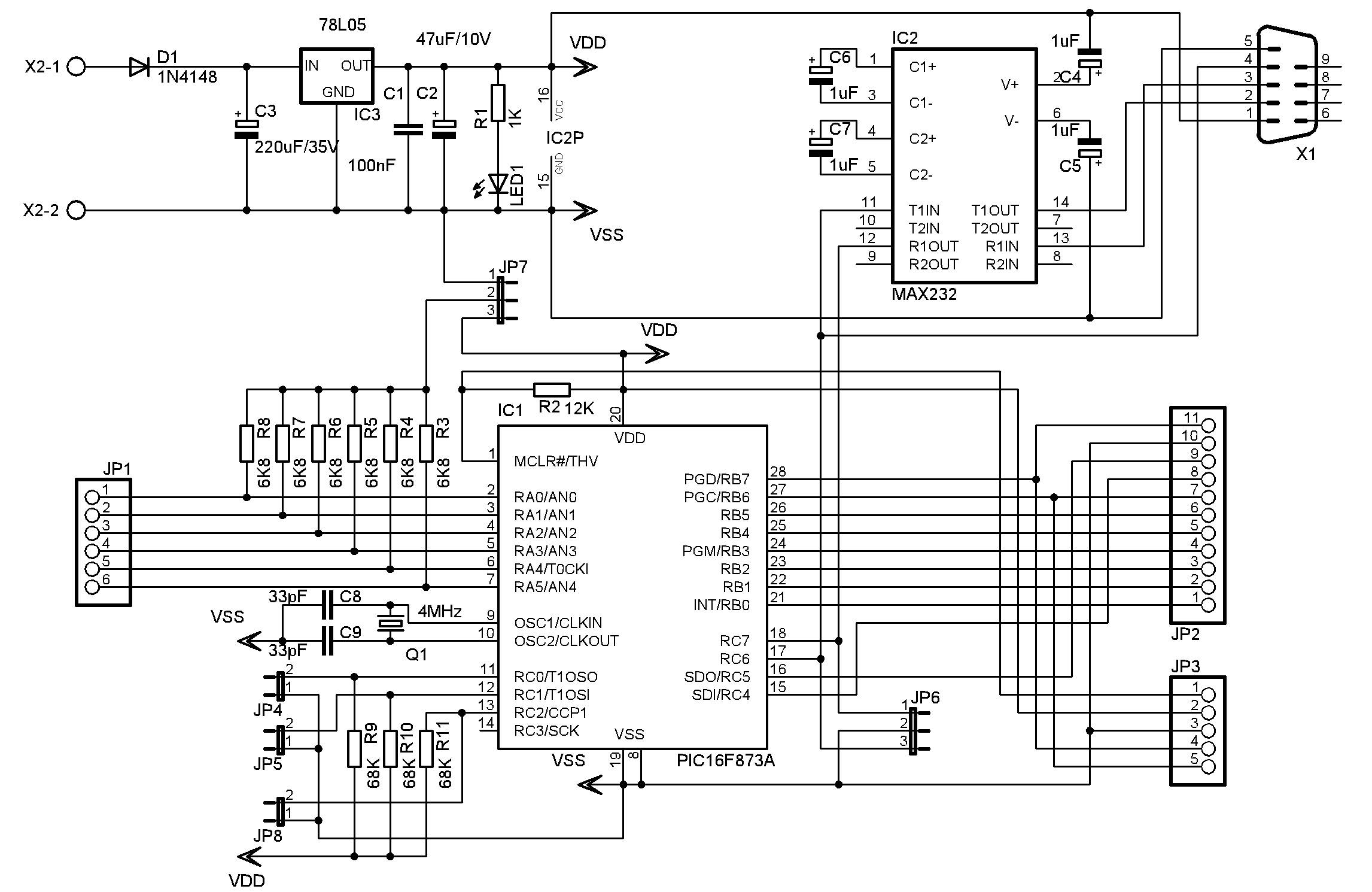
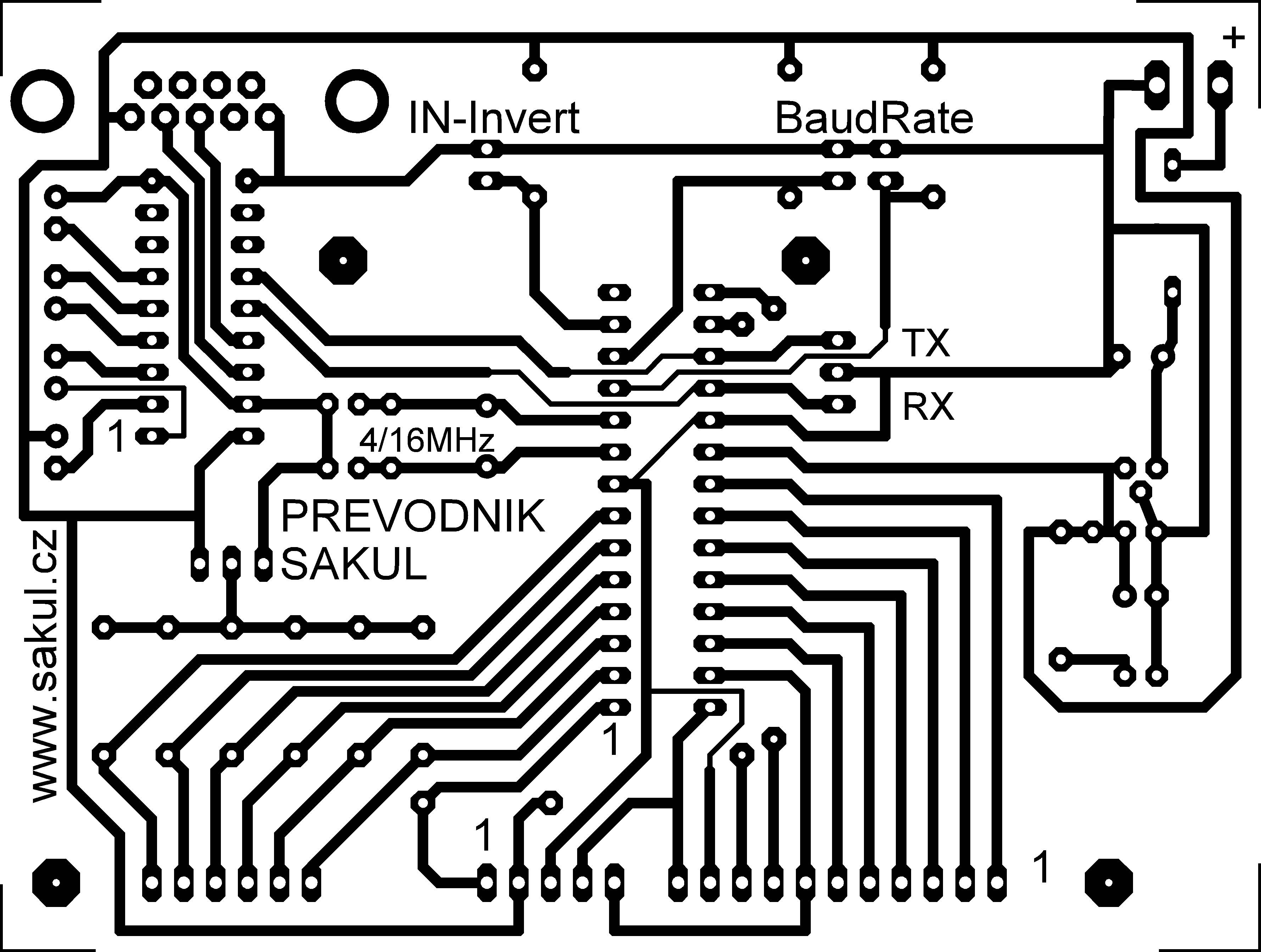
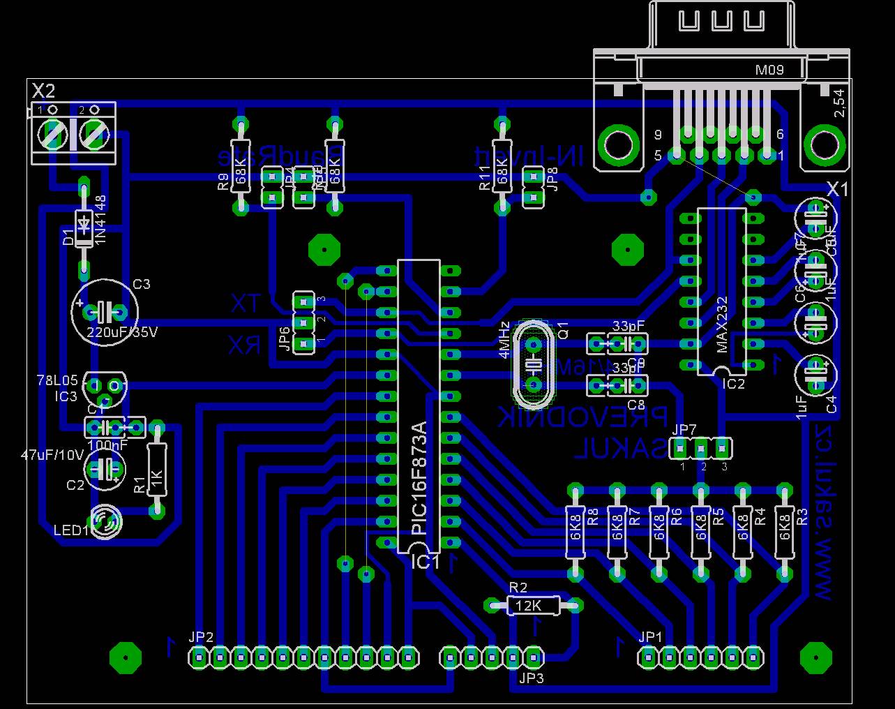
The converter module reads signals directly from the small stopwatch display and converts them into serial communication for the large display. It can be mounted above the stopwatch electronics using spacers. It includes a 5 V regulator, reverse-polarity protection, MAX232 RS232 interface and PIC16F873A microcontroller.
JP2 connects to the stopwatch display signals and should be wired directly to the processor outputs, before the limiting resistors. JP1 connects to the display anode control transistors. JP7 selects common-anode or common-cathode logic; the stopwatch uses common anode. Common-cathode operation is not supported in this version.
Documentation - Updated 2017-02-12
The complete construction documentation is available for download. It also contains the Eagle project files.
Changes
| 2017-02-12 | Old PCB versions were removed from the documentation. The package was updated and cleaned up. Use the files from the documentation package as the current source. |
|---|---|
| 2015-11-14 | A DEMO version of the display firmware was added to the documentation package. |
Declaration
This construction is original author work. Republishing on other websites or commercial use is not permitted without the author's permission. Linking to this page is allowed. The device is intended for personal use only and the author does not accept responsibility for damage caused by its use.
The construction uses microcontroller firmware protected by copyright. Sale of the firmware or derived commercial use is not allowed without the author's permission.