This board was created when I needed a new microcontroller module for my stopwatch construction. Unfortunately, none of the commonly supported microcontrollers in the Arduino IDE suited me well enough: some had too few pins, others had far more than I needed. After some searching I found MightyCore, which adds support for ATmega8535, ATmega16, ATmega32, ATmega164, ATmega324, ATmega644 and ATmega1284. The ATmega644 caught my attention the most, because it offers a useful number of pins, enough Flash memory and enough SRAM for reasonable money. That led to the idea of making a small board inspired by the Arduino NANO, but with an ATmega644 microcontroller: Sakulno NANO 644. Other compatible microcontrollers from the mentioned family can also be fitted, depending on what you need.
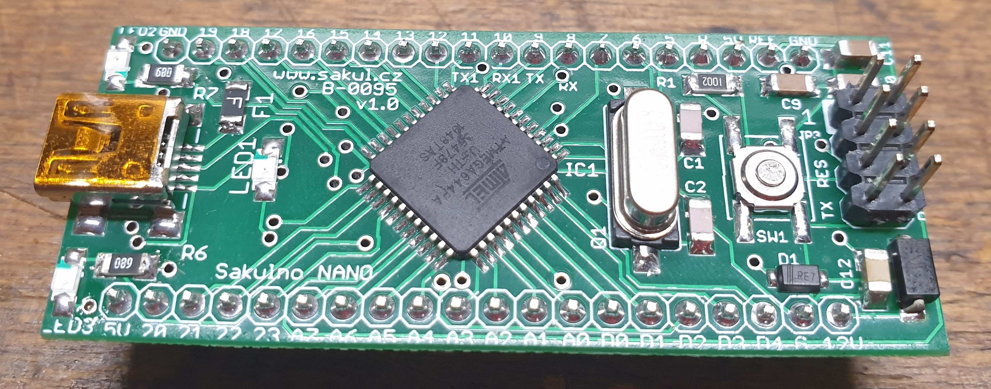
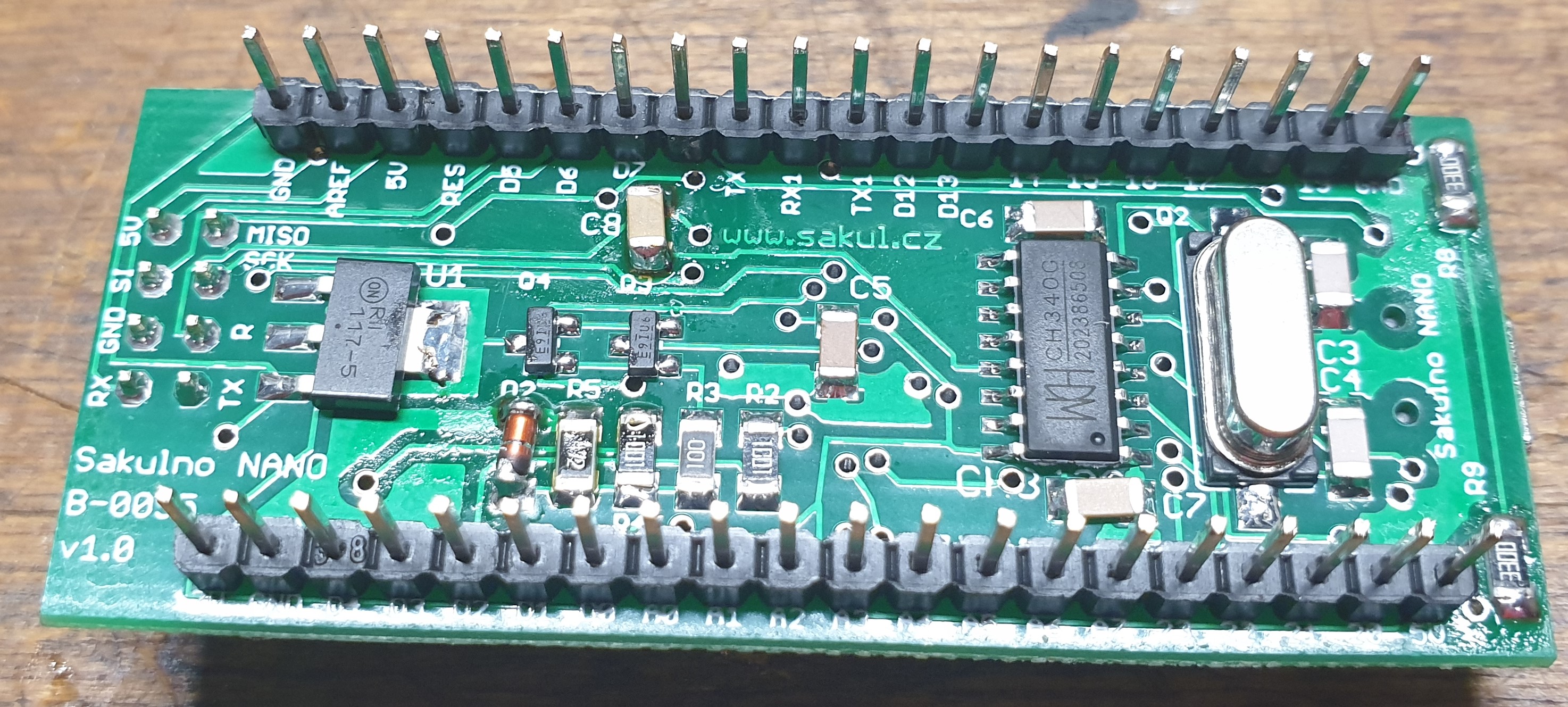
Technical Specifications
| PCB | B-0095 |
|---|---|
| Supply voltage | 7-15 V DC, marked as 12 V |
| Operating voltage | 5 V, max. 500 mA |
| Microcontroller | ATmega644, all variants P, PA, A |
| Flash memory | 64 KB, of which 1 KB is used by the bootloader |
| SRAM | 4 KB |
| EEPROM | 2 KB |
| Clock | 16 MHz |
| Analog inputs | 8x |
| Digital I/O | 32x, 6 of them with PWM support |
| Maximum output current | 40 mA, recommended max. 20 mA per pin and 200 mA total |
| Communication interfaces | 2x UART, I2C, SPI |
| Connection | Mini USB through CH340G to UART0 |
| Size | 61 x 15 x 10 mm, height without fitted connectors |
Construction Description
First of all, it is necessary to point out that this construction does not really have a function by itself. It gets its purpose only after it is used in another device and you upload your firmware into it. In principle, it is a microcontroller placed on a PCB with the necessary surrounding components required for operation. A mini USB connector is fitted, so the board can be powered and firmware can be uploaded through USB. All microcontroller pins are brought out to the sides of the board, allowing the module to be inserted into a more complex construction. To make the design more useful, it also fixes a design issue found on many Arduino boards: the voltage-management circuit on many of them can feed voltage back to the USB connector when the board is powered from an external source. According to the USB specification this is not acceptable, so this board solves it and prevents such backfeeding.
Schematic
Circuit Description
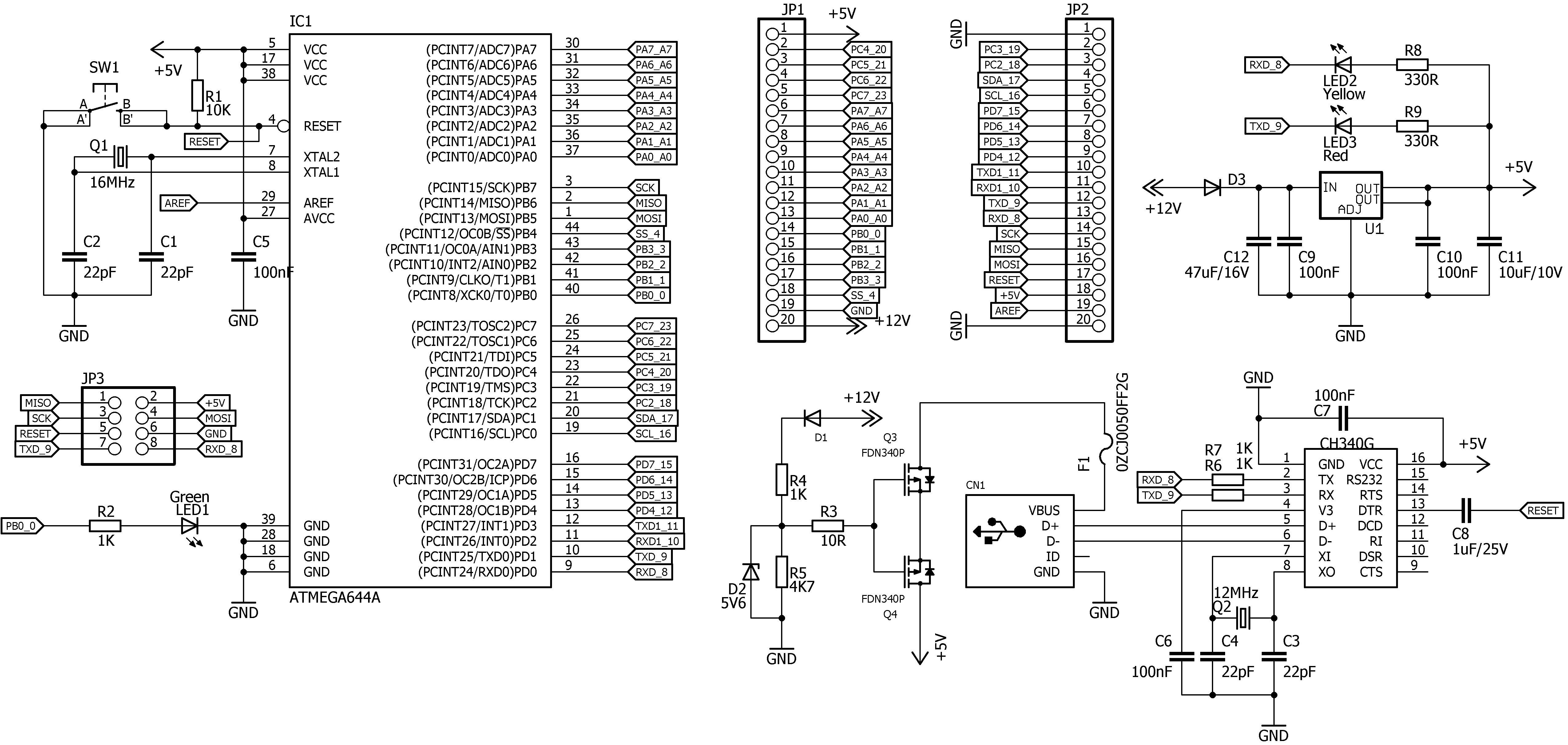
The whole design is dominated by the ATmega644 microcontroller (IC1). Without any hardware changes it is possible to use other compatible microcontrollers as well, such as ATmega8535, ATmega16, ATmega32, ATmega164, ATmega324, ATmega644 and ATmega1284. The ATmega8535, ATmega16 and ATmega164 variants usually make less sense because of their smaller Flash memory. Most microcontroller pins are brought out to solder points along the sides of the PCB, where pin headers JP1 and JP2 can be fitted. The crystal oscillator consists of crystal Q1, 16 MHz, and capacitors C1 and C2. A 16 MHz crystal is used, but other frequencies can be used as well, or the microcontroller can be switched to the internal oscillator. The detailed list of usable clock options is shown later. The reset circuit consists of button SW1, resistor R1 and, through C8, the DTR output of the CH340G (U$1), which is used during firmware upload over USB.
The CH340G USB-to-TTL converter changes USB communication to UART0. It was chosen because it is well supported, for example under Windows 10, is easy to obtain and inexpensive. The converter uses crystal Q2, 12 MHz, and capacitors C3, C4, C6, C7 and the already mentioned C8. A mini USB connector was selected. It is not the most common connector anymore, but I had a stock of them and wanted to use them. A future version could use micro USB instead.
The 5 V from the USB connector is routed through PTC fuse F1 into the voltage-management circuit, which uses two P-channel MOSFET transistors (FDN340P). These transistors are controlled through divider R4/R5 and zener diode D2, 5V6. Correct polarity is ensured by diode D1. This circuit prevents the 5 V from the integrated stabilizer U1 (LM1117) from reaching the USB connector. The stabilizer itself allows the board to run from approximately 7-15 V. Its input is protected against accidental reverse polarity by diode D3. Capacitors C9-C12 provide filtering.
The remaining parts are LED2 and LED3, which indicate communication on UART0, and LED1, which is connected to one processor output pin similarly to common Arduino boards. Connector JP3 is used for an ISP programmer when a bootloader or firmware needs to be uploaded directly. The connector has more pins than a usual ISP header because UART0 is also brought out there, which can be useful when uploading firmware through an external serial converter.
Assembly Plan
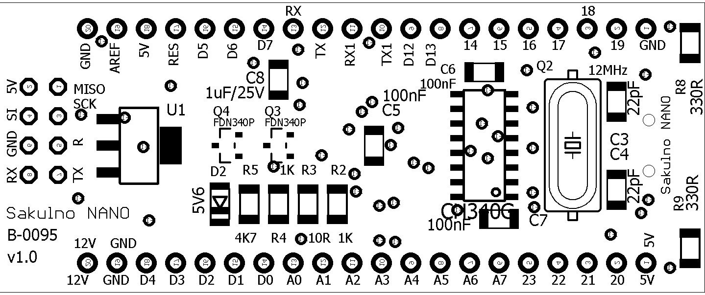
PCB Drawing
I do not publish PCB drawings as simple images, because this is a double-sided board with plated-through holes and producing it from image documentation is not practical. The documentation package at the end of the article contains the complete Eagle 7.7 project, from which production data can be exported.
Assembly Procedure
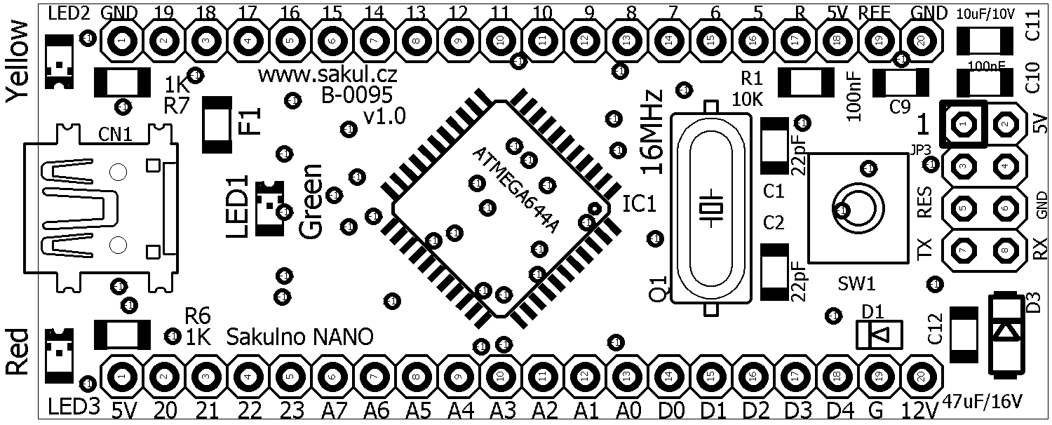
If you decide to assemble the PCB yourself, the best method is to fit the complete TOP side with SMD components and solder it in a reflow oven, or with hot air, and then solder the BOTTOM side manually. The THT parts, mostly connectors, should be fitted last. Of course, the whole board can also be soldered manually with a fine soldering iron. In that case it is important to work carefully, avoid solder bridges and inspect all joints. I recommend starting with the microcontroller and then continuing from the smallest to the largest parts on the TOP side, followed by the BOTTOM side. After assembly, check everything thoroughly.
Initial Bring-up
If everything is assembled correctly and no problem is found during inspection, bring-up can begin. First connect power through a USB cable. Connect a voltmeter to one of the pins marked 5V and GND and check that the voltage is correct. If everything is fine, disconnect USB and connect preferably 12 V from a laboratory supply to the pins marked 12V and GND. Set the supply current limit to 50 mA, or to the smallest value the supply allows, and switch it on. Current consumption should be around 10 mA. If it is much higher, there is a problem. If the current is correct, measure the 5 V rail. Then verify that there is no voltage on fuse F1 when powered externally. This completes the first check and the microcontroller can be initialized.
Bill of Materials
The exact bill of materials including package sizes is available in the electronic documentation and in the PartList.
MightyCore
Before bringing the microcontroller to life, support for the used microcontroller must be installed in Arduino IDE. I recommend using Arduino IDE in the newest suitable version; MightyCore requires at least version 1.8.7. I prepared this environment as part of the documentation package, so it is enough to extract it, ideally with 7-Zip, to any location and start using it. For completeness, the installation of MightyCore is also described below.
Download the newest Arduino IDE from https://www.arduino.cc/. For Windows, use the Windows ZIP file for non admin install version. Extract the archive to any folder. Before starting arduino.exe, create a new folder named portable in the same directory where arduino.exe is located.
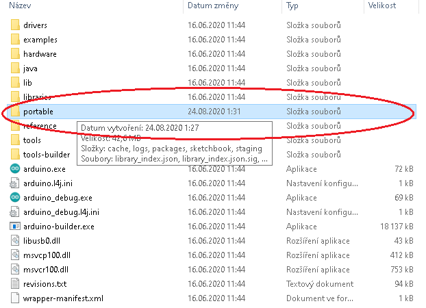
This folder makes Arduino IDE store additional files directly there instead of somewhere in the user profile. Thanks to that, the whole environment can be placed on a flash drive and moved between computers while keeping your projects with it.
After creating the portable folder, start Arduino IDE using arduino.exe. First update all board definitions and libraries. Then open Preferences, enable line numbers and verbose upload output if desired, and mainly add the following URL to Additional Boards Manager URLs:
https://mcudude.github.io/MightyCore/package_MCUdude_MightyCore_index.json
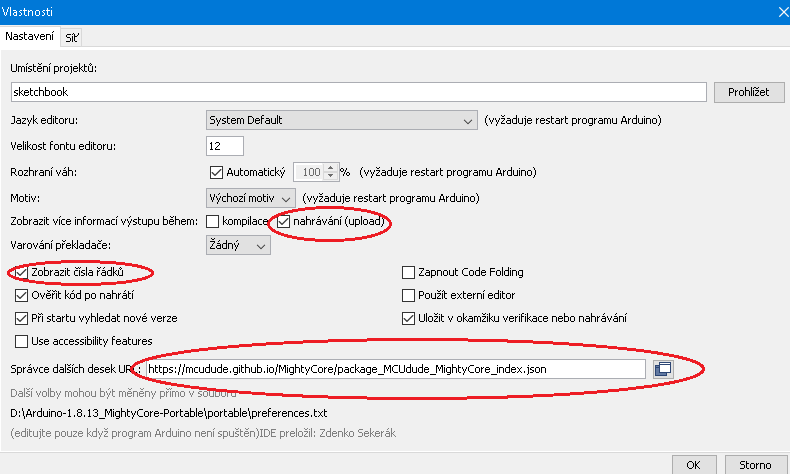
Confirm with OK. Then open Tools / Board and click Boards Manager.
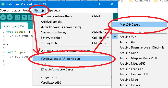
In Boards Manager select All in the Type field and search for MightyCore. The package with support for the required microcontrollers will appear. Click Install and wait until everything is downloaded and installed.
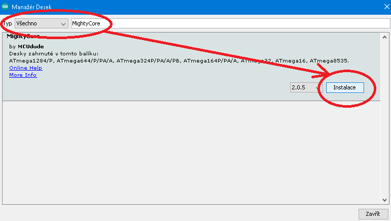
After closing the manager, a new MightyCore item appears under Tools / Board, and it contains all supported microcontrollers.
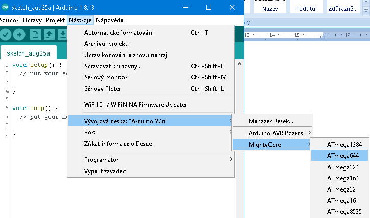
Select the microcontroller that is fitted on your Sakulno NANO, most likely ATmega644.
Fuse Settings and Bootloader Upload
Once MightyCore support is installed, the correct parameters must be set and the bootloader must be uploaded to the microcontroller. This is necessary even if you do not plan to use the bootloader, because the fuse bits are configured when the bootloader command is executed. In the Tools menu, with ATmega644 selected, set the parameters according to the following image.
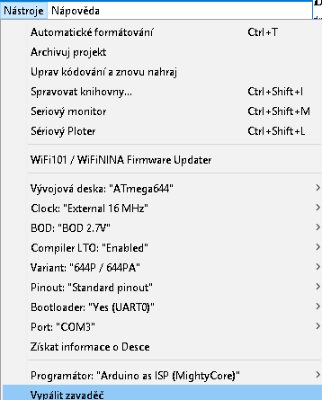
Clock: The default should be External 16MHz. Sakulno uses a 16 MHz crystal, so this setting is correct. Other supported oscillator variants and frequencies are available in the menu. For details, study the MightyCore documentation.
BOD: This sets the minimum voltage at which the microcontroller is held in reset by brown-out detection. If the supply voltage drops too low, unstable operation can occur. In most cases the default 2.7 V setting is suitable.
Compiler LTO: I recommend switching this to Enabled. It can significantly reduce the occupied program memory. Arduino IDE 1.6.11 or newer is required for this function.
Variant: Select the exact variant of the used microcontroller. The marking is printed directly on the chip. In my prototype Sakulno NANO 644, for example, the microcontroller is ATmega644PA. If a wrong variant is selected, upload will fail with a signature mismatch error.
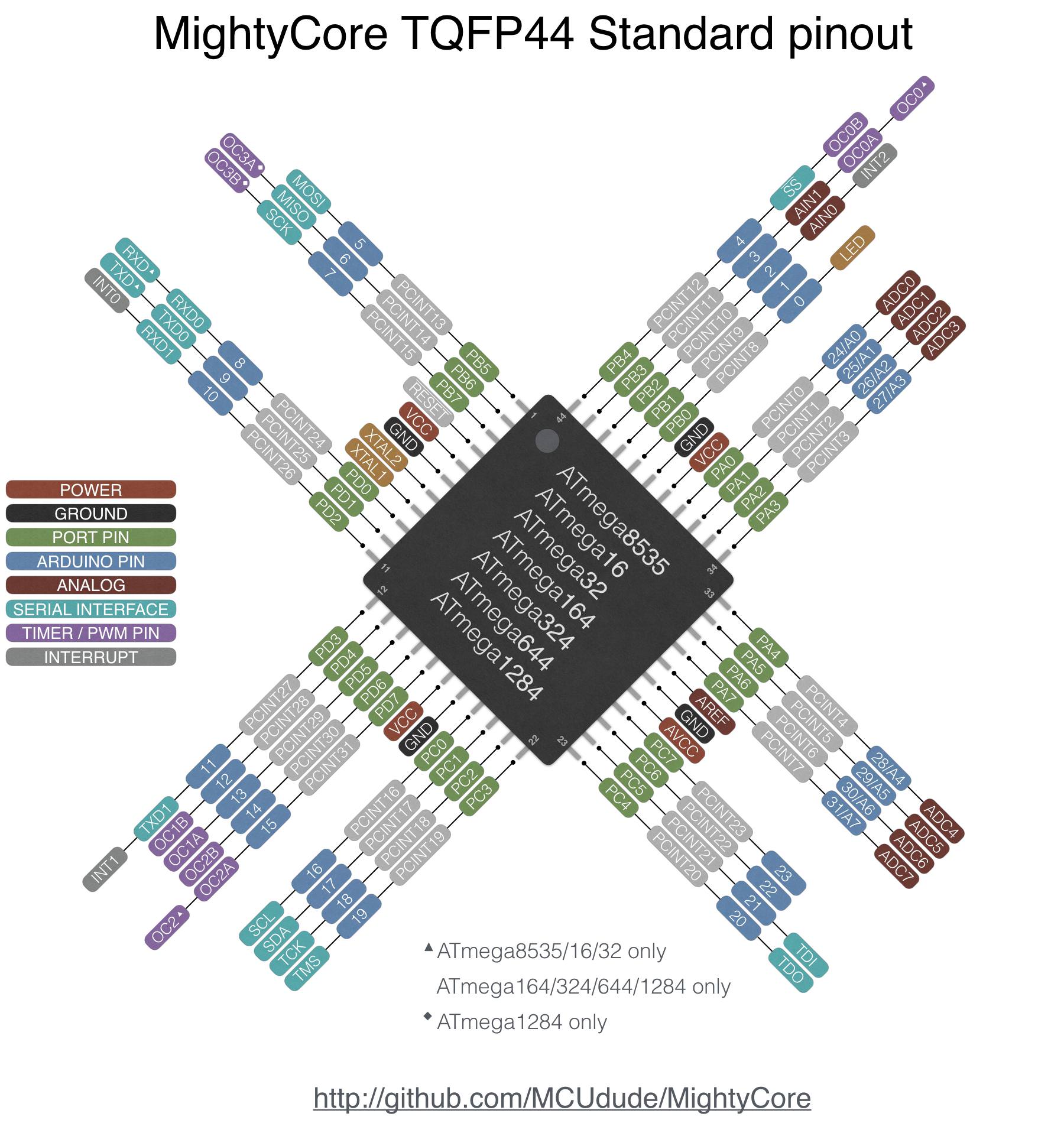
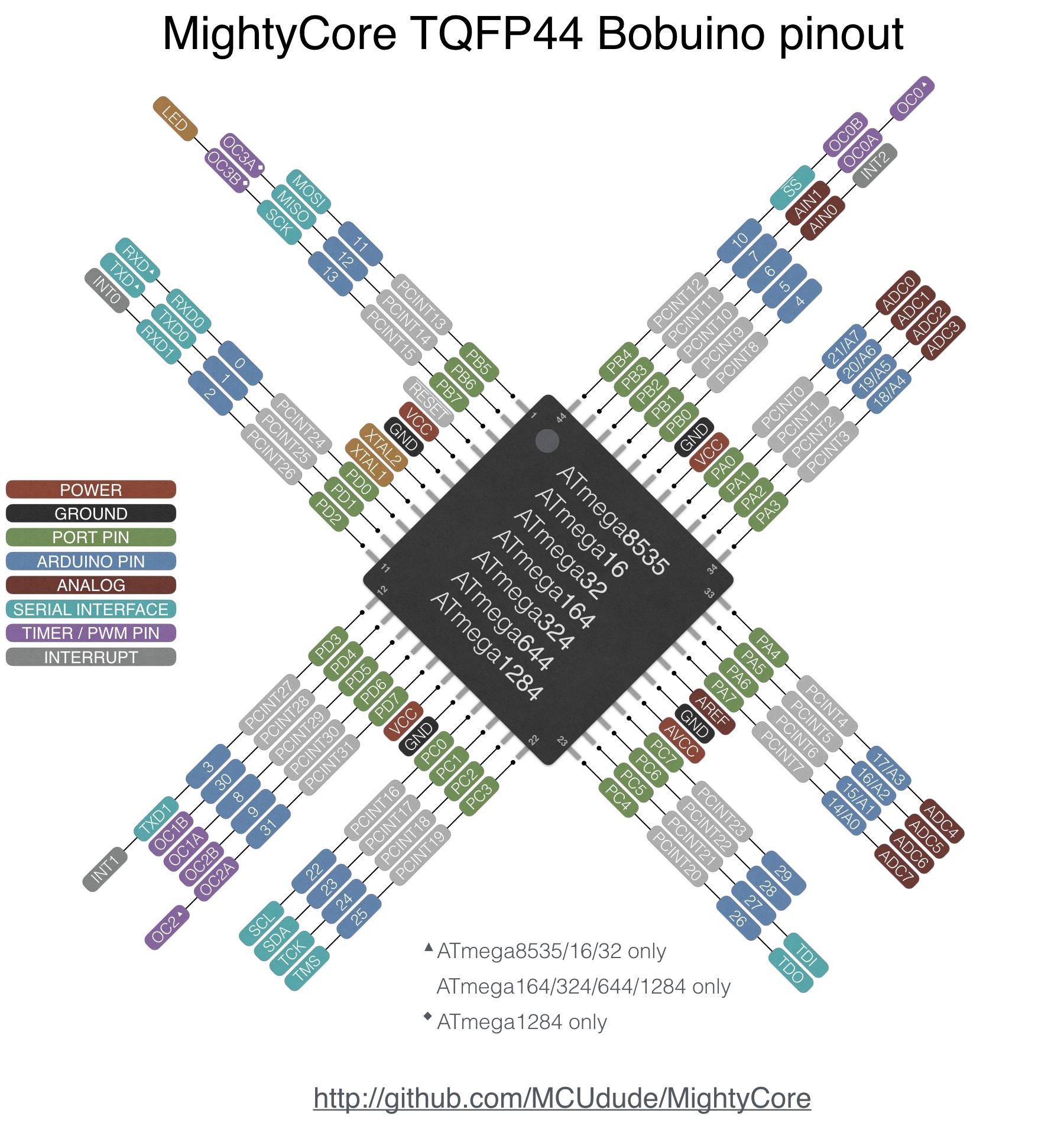
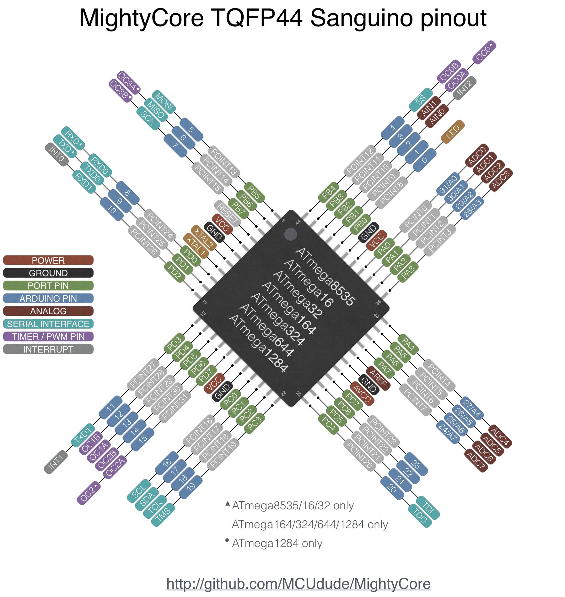
Pinout: I use Standard pinout, but other variants can be selected. This setting is important if your programs use numeric pin definitions. MightyCore also allows pins to be addressed by their actual names, such as PIN_PB0.
Bootloader: This sets whether a bootloader will be uploaded together with fuse settings. The bootloader allows later firmware updates through USB or the selected UART without an ISP programmer. For Sakulno NANO this must be set to Yes (UART0), because the USB-to-TTL converter is connected to UART0. If you plan to upload firmware only through a programmer, select No Bootloader.
Port: This selects the COM port used by the PC. During the first initialization it refers to the connected ISP programmer, not to the Sakulno NANO board itself.
ISP Programmer Selection
The next step is choosing the programmer used for uploading the bootloader and setting the fuses.
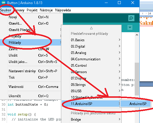
I often use an Arduino NANO board that I reflashed with the UNO bootloader and then uploaded the File / Examples / ArduinoISP sketch into it. This turns the common Arduino board into a programmer. The reason for replacing the original NANO bootloader with the UNO bootloader was that ArduinoISP did not work correctly for me with the original NANO bootloader. A direct Arduino UNO programmer is therefore a good choice. Connect MOSI, MISO, SCK, 5V and GND from the UNO to Sakulno NANO, and connect the Sakulno NANO reset pin to D10 on the UNO. Any other supported programmer can also be used.
Select Programmer: Arduino as ISP (MightyCore). If the programmer is connected to the Sakulno NANO board and to the PC, select the COM port of the ISP programmer and click Burn Bootloader. If everything is correct, the bootloader and fuse configuration are uploaded within a few seconds. The Arduino IDE status output confirms success and LED1 on the Sakulno NANO should start blinking.
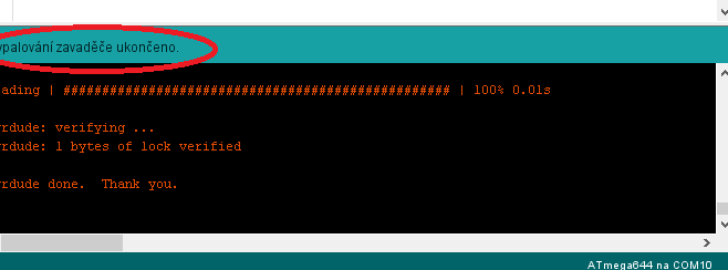
At this point Sakulno NANO behaves like a regular Arduino board and can be programmed through the USB cable.
Pinouts
Using XLoader
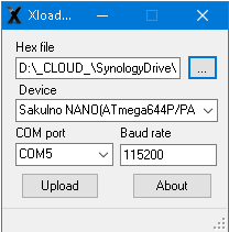
XLoader is primarily used to upload firmware in HEX format, meaning already compiled firmware, into Arduino boards. By default it does not support the ATmega644PA used here, but support can be added quite easily. I added Sakulno NANO to the list of supported boards in two variants. The first should support ATmega644 and 644A. The second supports ATmega644P and PA.
The modified XLoader with Sakulno NANO support is included in the documentation package. I like using it for projects where users may need to update firmware later without compiling it themselves.
Troubleshooting
Many things can go wrong during bring-up, so the most common issues are worth mentioning.
1. Processor reset problem during firmware upload over USB. I ran into this when I started using MightyCore microcontrollers. My constructions usually use a CH340G USB-to-TTL converter, which resets the target through DTR. In normal operation this pin is high. During firmware upload it goes low and remains low for the whole upload. Without a capacitor this would hold the microcontroller permanently in reset. A capacitor is therefore placed between DTR and reset, usually 100 nF. With ATmega644 and ATmega1284, however, that value was not sufficient in my tests. The capacitance must be at least 220 nF and ideally 330 nF. In the final design I used C8 with 1 uF, a common 1206 ceramic capacitor rated for 25 V.
2. During first initialization the connected chip reports a wrong ID. This is a common problem. Before uploading either bootloader or firmware, the tool checks whether the connected chip matches the compiled firmware target. If the expected ID does not match the ID read from the programmed component, upload fails. The most common causes are: the wrong microcontroller variant is selected in Arduino IDE, the read ID is invalid or belongs to another chip, or no ID is returned at all. First check the exact selected variant, for example ATmega644PA versus ATmega644. Then check all wiring and make sure the programmed chip is supplied within its operating-voltage range during the whole process. Long low-quality USB cables can cause a large voltage drop, so adding external power may help. If only zeros are returned, communication with the chip was not established, most often because of wiring.
Documentation
Finally, you can download the complete build documentation here. It includes the Eagle project, Arduino IDE with installed MightyCore support and a test program for the processor in XLoader.
Notice
This construction is original author work. It may not be copied to other websites or used commercially without the author's permission. Linking to this website and to this construction is allowed. For more information, contact me. I also accept no responsibility for the device behaviour or any damage caused by using it. The device is intended only for personal use. Any sale is not allowed without the author's permission.