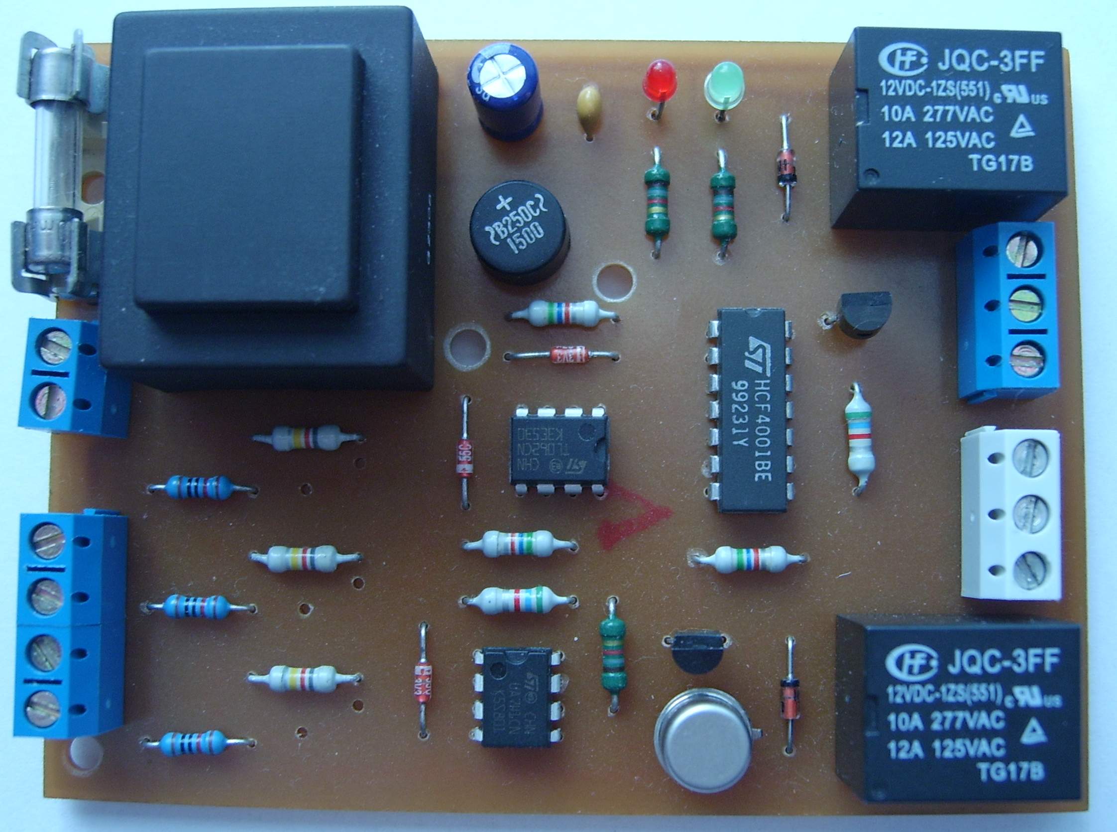
I designed this module as a replacement for a classic mechanical float switch. Several years ago I bought a portable air conditioner. This unit is fully mechanical, unlike very similar models that are equipped with remote control and digital temperature setting. Although my air conditioner is fairly simple, it has one very useful feature: water cooling. As I later found out, many manufacturers do not use water cooling. Using condensed water for cooling is very useful, and another advantage is that during all the years I have had this air conditioner, I have never had to drain excess water. Because the water is used for cooling, it evaporates again.
As mentioned above, my air conditioner is mechanical and uses a three-position float switch to sense the level of condensed water in the tank. The first position, the lowest level, turns the water pump off. The second position, the working level, turns the water pump on. The pump moves water from the tank into the cooler, where it flows through by gravity and returns back to the tank. The third and last float position is the emergency level. It turns the air conditioner compressor off and signals that the tank is full. This situation has never actually occurred.
Everything still works without a single problem, apart from one small drawback: the water tank capacity is not sufficient. When the level rises to the second float position, the pump turns on and starts pumping water from the tank into the cooler. Since this is not a closed and sealed loop, the cooler is empty when the pump is not running. Only after the pump starts does water begin to flow through it. However, before the water flows through the cooler and returns to the tank, the tank is already empty and the float turns the pump off. As soon as the water returns from the cooler into the tank, the level rises again and the whole cycle repeats until enough water evaporates and the pump no longer switches on. That is the real problem. The clicking float contacts and constant pump switching are quite disturbing.
At first I wanted to solve it by adjusting the float so that the working range would be larger and the water would have enough time to return to the tank without constant switching. The tank capacity itself would allow such operation, but I ran into the problem of how to adjust the float. After several unsuccessful attempts, I decided to design electronic level sensing, pump switching and emergency level evaluation. The construction of this water level monitor is described below.
Level Sensing
First, let us start with the schematic shown below.
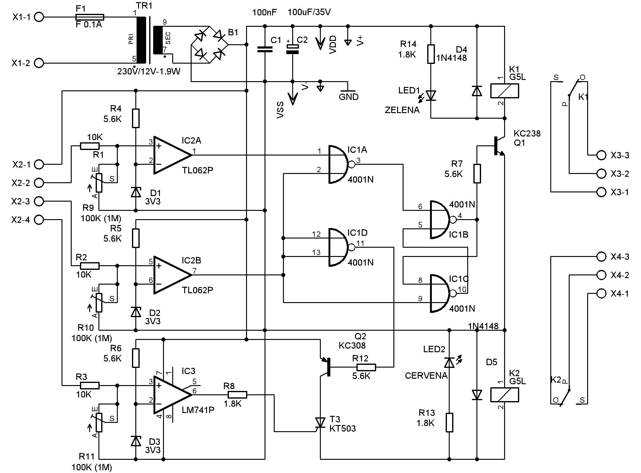
The schematic shows that the whole device is quite simple. Three comparators are used for level sensing. Trimmers R9, R10 and R11 set the sensitivity and must be adjusted so that the device reliably detects the water level. For ordinary water, a value of around 100K is sufficient. For distilled water, higher values shown in the schematic are required. The board also allows fixed resistors to be fitted if the device is used permanently and sensitivity adjustment is not needed.
The Zener diodes together with their resistors create reference voltages. One reference voltage source for all comparators would probably be enough. The 4001 logic forms a latch, which drives pump relay K1 through transistor Q1. Relay K2 switches when the level reaches the critical value. There is not much more to explain, because the device is relatively simple.
Operation
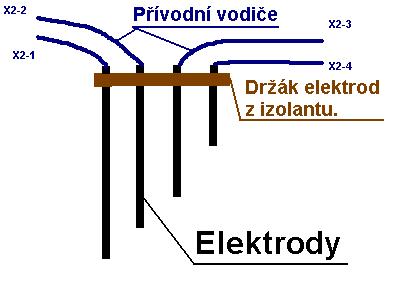
The device works as follows: the electrode connected to terminal X2-1 provides the positive voltage. The electrode on terminal X2-2 senses the minimum level in the tank. When the water reaches the electrode on terminal X2-3, relay K1 switches on and can, for example, start the pump. At this point the level starts to fall again and the pump turns off only when the water drops below the electrode on X2-2. Then the whole cycle repeats.
If the pump fails, or another problem causes the water to rise up to the electrode connected to terminal X2-4, relay K2 switches on. This relay can trigger an alarm or shut the device down. It is important to note that relay K2 can switch only when the electrode on X2-3 is also under water. When the level drops below X2-3, relay K2 turns off and the device returns to normal operation.
PCB and Component Placement
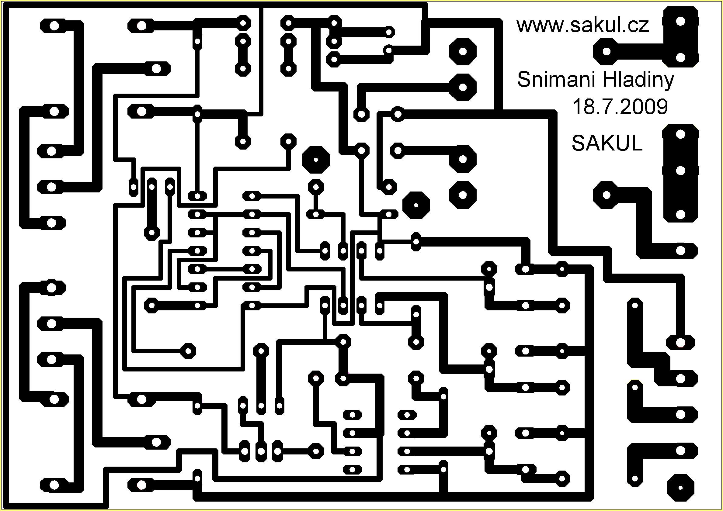
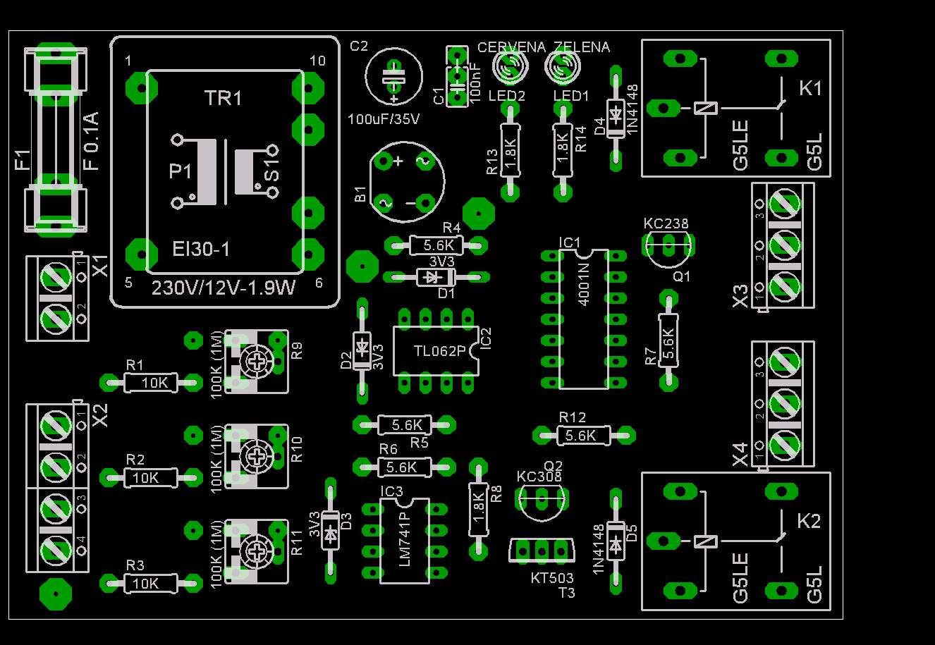
The printed circuit board is a single-sided board measuring 100x70mm. It is also possible to use 100x75mm boards that already have a photosensitive layer applied. Assembly should not cause any major problems. The only thing to watch out for is unwanted solder bridges around the integrated circuits, because some traces are routed between their pins.
Testing and Adjustment
The whole device is powered directly from the mains, so extra caution is necessary. If no mistakes are made during assembly, the device should work on the first try. The only required adjustment is the sensing sensitivity. In my prototype I fitted fixed resistors with a value of 820K. They reliably detect distilled water, or more precisely the water in the air conditioner's condensate tray, for which this device was built as a replacement for the original mechanical float switch.
Electrode Construction
The electrode construction must be adapted to each particular application. Just one small warning: I have seen electrodes designed directly as a printed circuit board several times. This is completely unsuitable, because even after the level drops, the board remains wet and it is difficult to adjust the circuit so that it works reliably. Wire electrodes are more suitable, with their ends cut exactly to the required water level height. An example electrode solution is shown below:
Documentation
Finally, you can download the complete construction documentation here. The archive also contains the Eagle project.