Technical Specifications
| Supply voltage | 8-15 V AC/DC |
|---|---|
| Current consumption | approx. 100 mA |
| Internal display | Six-digit LED display |
| External display | LED display with up to seven digits |
| Display resolution | 99:59:99, minutes:seconds:hundredths |
| Number of times | 2 final times, left and right target, + 5 split times |
| PC communication | USB or Bluetooth module |
| External display communication | Cable or wireless connection |
| Inputs | Optically isolated |
| Control | Single button or input |
Construction Description
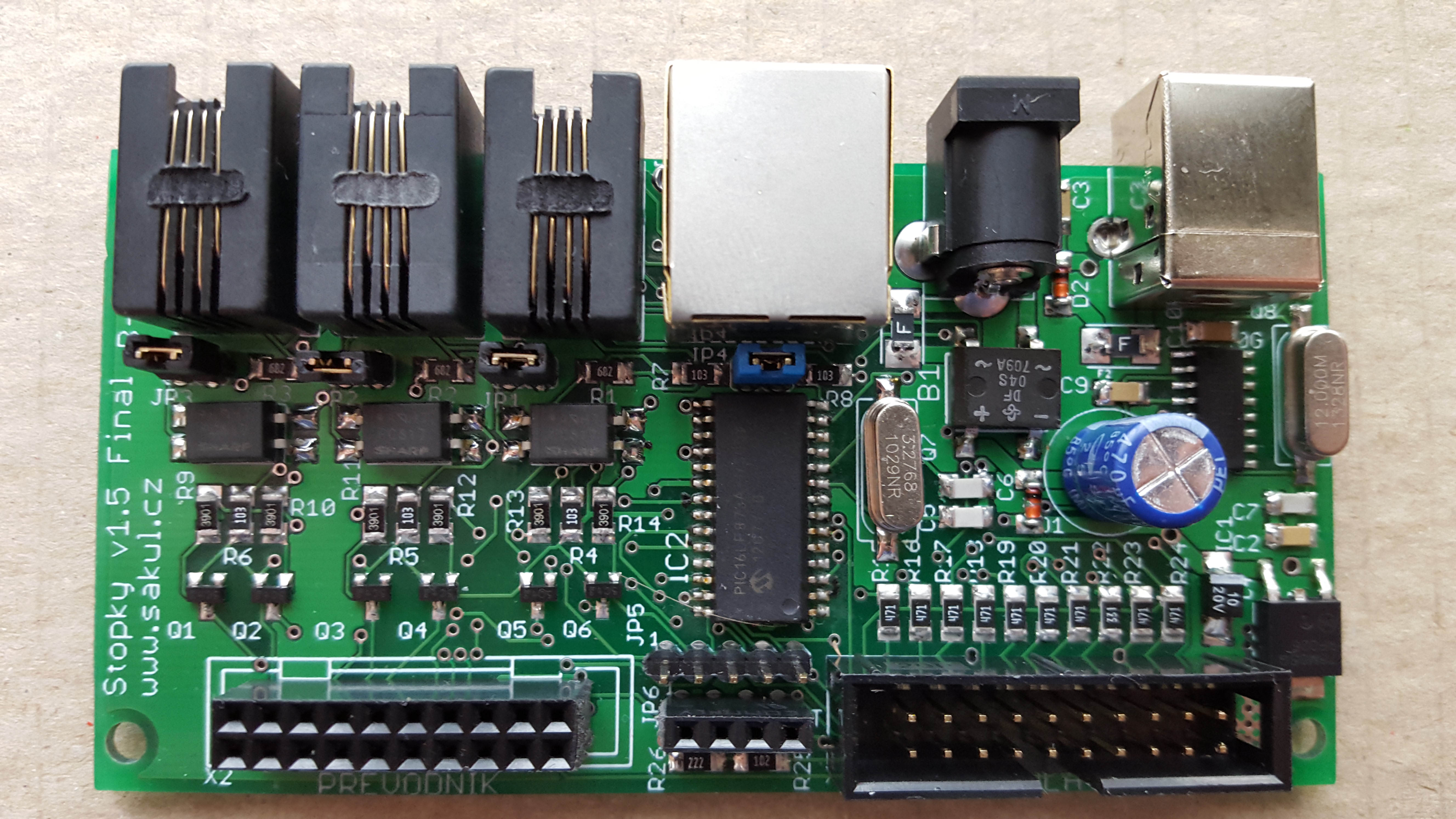
This stopwatch is based on the popular stopwatch construction built with classic THT components. Over time the stopwatch was improved and this version is its final form. Most components are in SMD packages, which made the construction smaller and partly cheaper. It was therefore possible, while keeping the same price level, to add a USB converter for communication with a connected PC, where measured times can be sent. The stopwatch can also be powered from the USB connector, but this is not recommended for normal operation. It is better to power it through the supply connector with 8-15 V DC or AC. The stopwatch contains a bridge rectifier, which ensures correct power supply under all conditions, so DC polarity does not matter and is therefore not marked.
The stopwatch has three optically isolated inputs. Two inputs are used for the targets used in fire brigade sport and one input is used for the control button. For this reason the stopwatch has three separate inputs and one combined connector. This solution is maximally universal and, if needed, an adapter with screw terminals can be connected to the combined connector.
The construction is still split into a processor board and a display board. This greatly simplifies installation into almost any enclosure. The recommended enclosure for this version is KM60 and equivalent boxes. The box is fitted with a front panel made from red plexiglass and a rear panel with milled holes and labels.
If required, a converter module for a large external display can be inserted into the processor board. The display can then be connected with a standard telephone cable up to a distance of approximately 15 m. Wireless connection is also possible between the stopwatch and the external large display, and also between the stopwatch and a PC. Everything is optimized for the popular HC-06 Bluetooth modules, but with a small modification other modules such as HC-11 or HC-12 can also be used.
Stopwatch Operation
The fire brigade stopwatch is activated by connecting the supply voltage. If everything is correct, initialization starts and is indicated by all display segments flashing in sequence. Zeroes are then shown on the display: 00:00:00. At the same time the target limit sensors are tested to check whether they are ready for start. If the target sensors are correct, red LEDs in front of the display light up, LED1 and LED2 before the tens-of-minutes digit. If one of the limit sensors is in the wrong position or configuration, the corresponding LED does not light and the target or the wiring from the target to the device must be checked. This configuration depends on the limit-sensor detection setting, which is selected inside the device by fitting jumper JP4.
After successful initialization the stopwatch is ready to start measuring. The measurement is started with the START button, connected to input J3. The time starts running and the LEDs indicating the reached target sensors switch off. If START is pressed again during measurement, a split time is stored. Up to five split times can be stored this way. The stopwatch stops only when both target sensors are reached. At that moment the time stops and the display briefly flashes, which means the times are sent to the PC. After that, short presses of START browse through the stored split times. Because the measured times are usually in tens of seconds, the first two display digits are used to identify the split time. For example, 3-10:83 means split number 3 followed by the split time. All five split times can be displayed this way. Final target times are displayed in full and the corresponding target is identified by the associated LED. Browsing through saved split times is possible repeatedly until the stopwatch is reset or until a power failure resets the whole device. Reset is also performed with the START button, but the button must be held for about 3 seconds. The reset is visible on the display and its sequence is the same as initialization.
Schematic - Processor Board
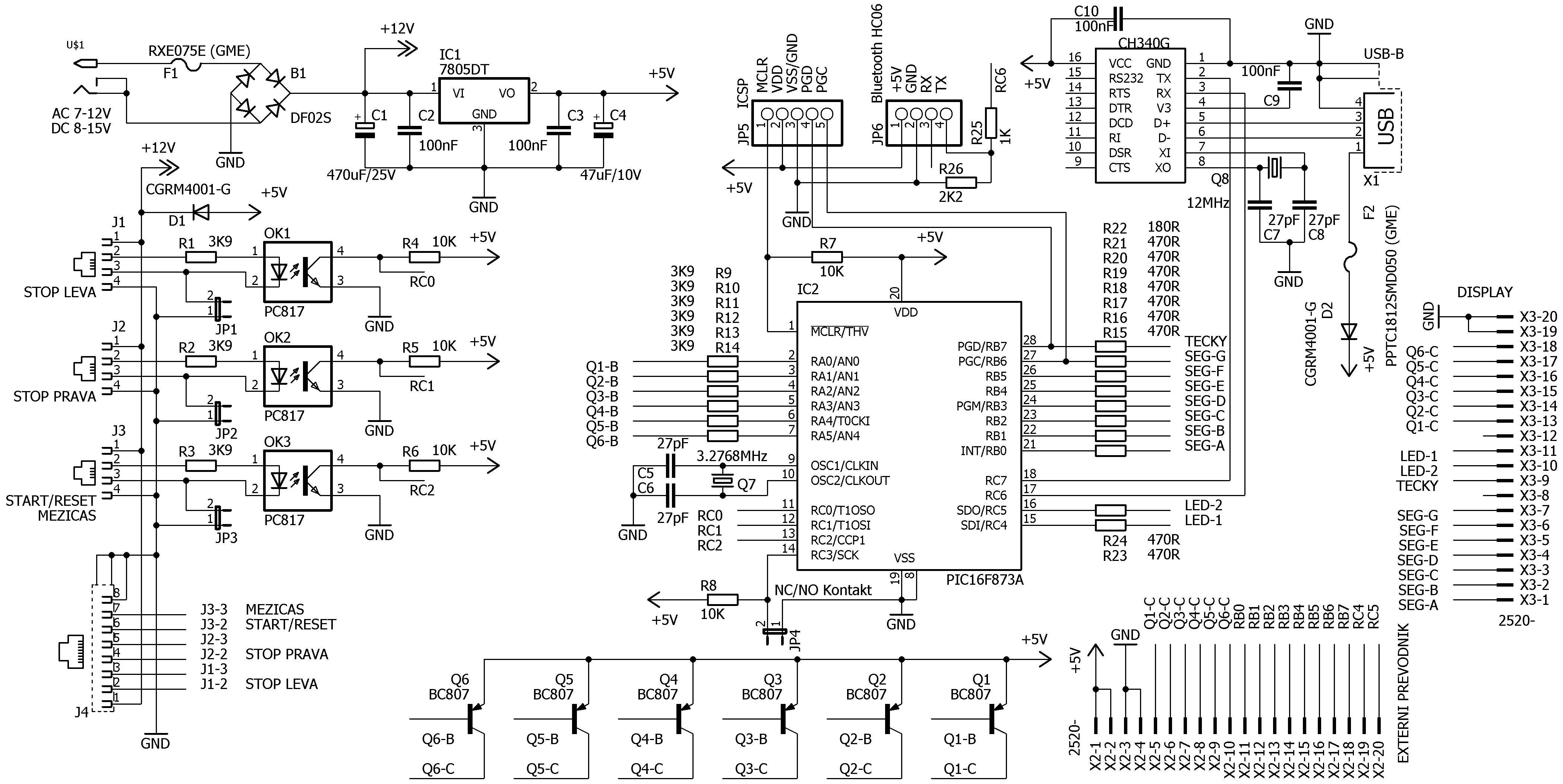
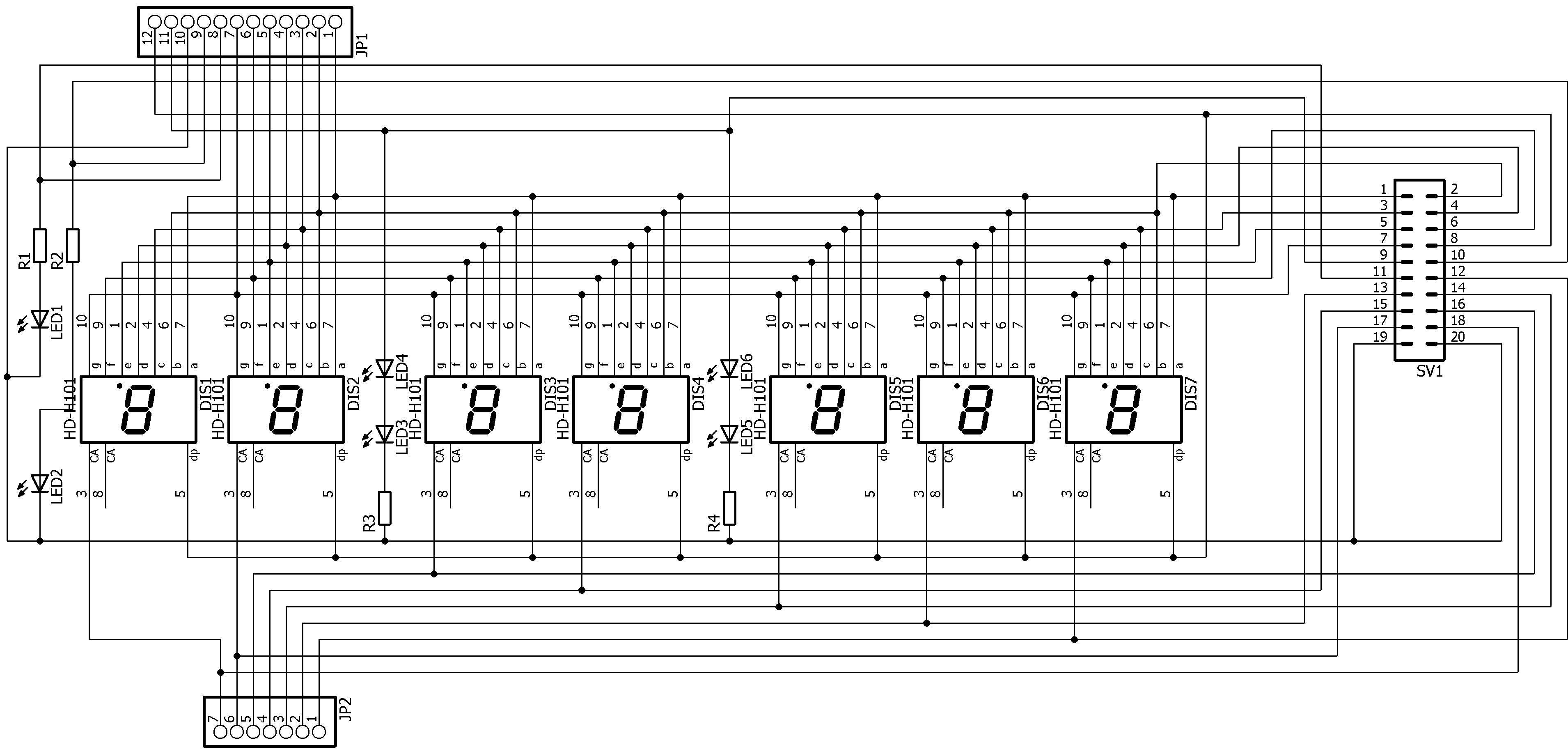
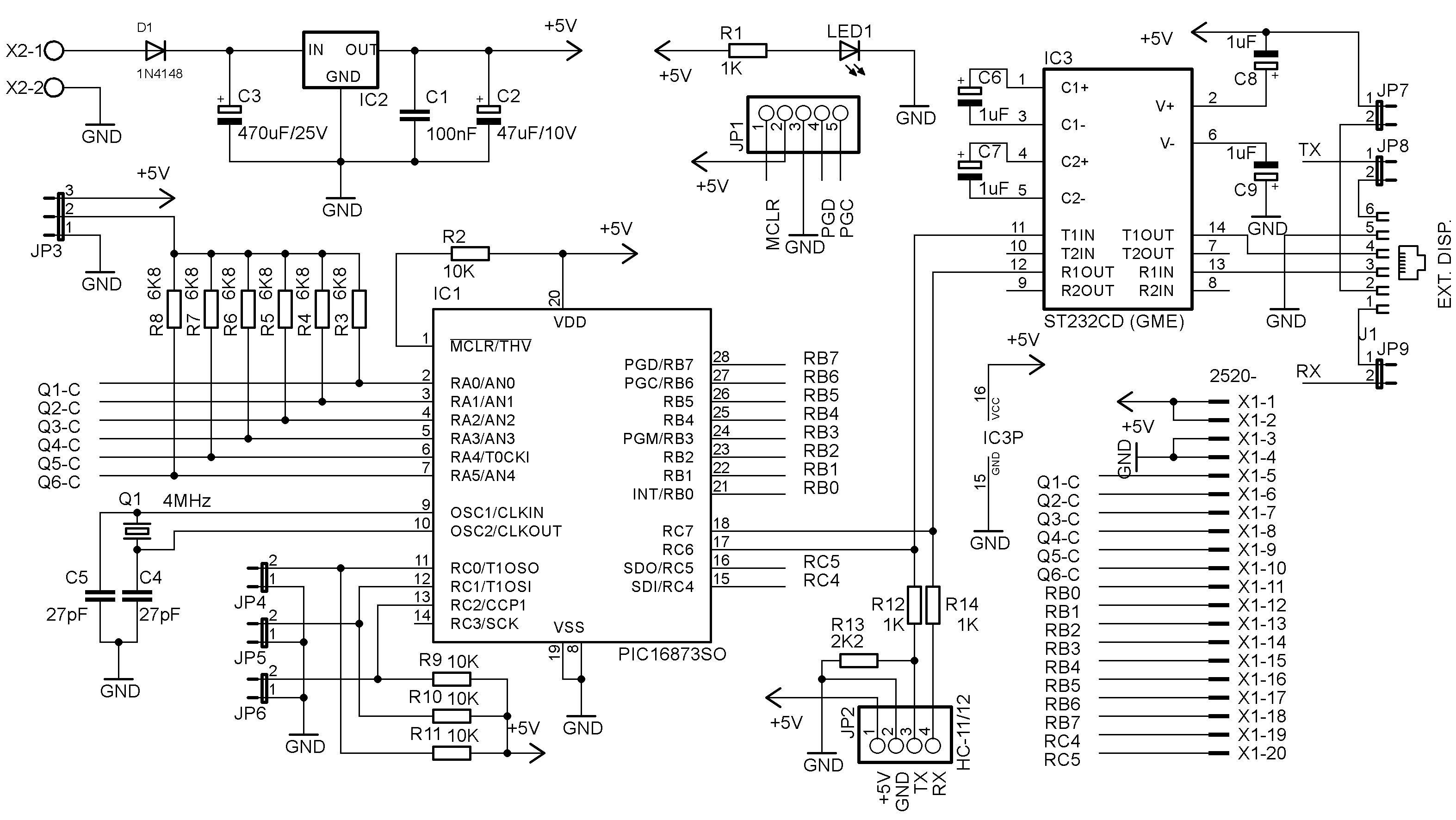
The schematic and the whole construction are divided into three parts: processor board, display board and converter board. The figure above shows the processor board schematic.
Schematic - Display Board
Schematic - Converter Board
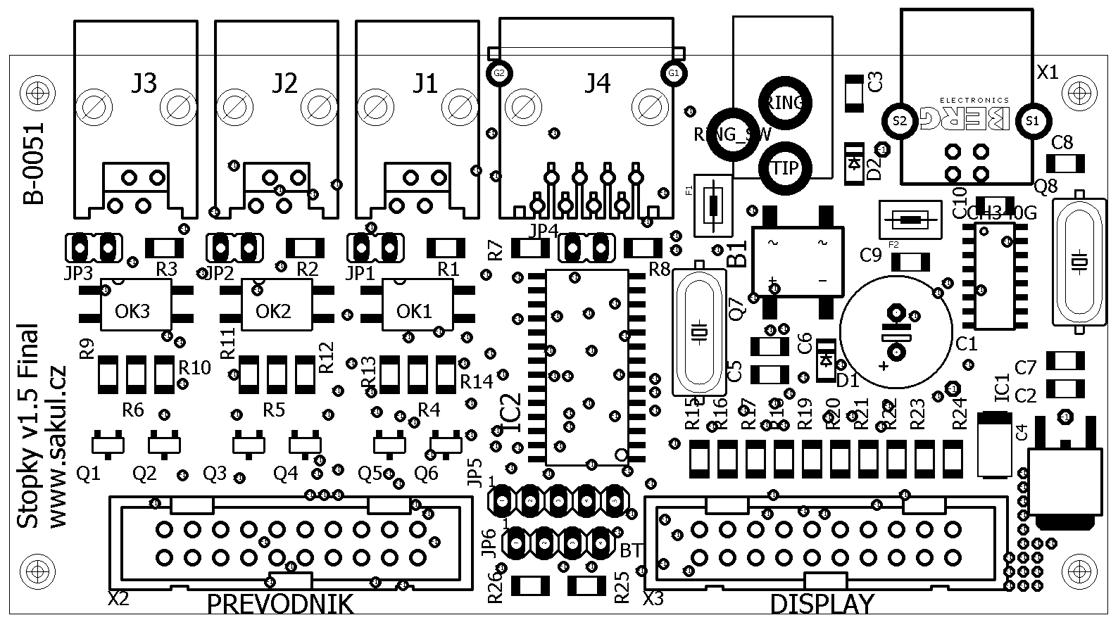
Assembly Plan - Processor Board
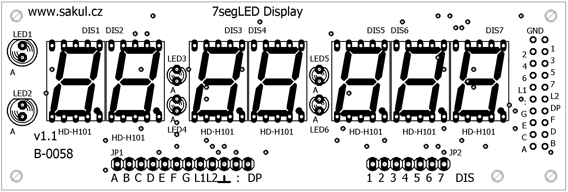
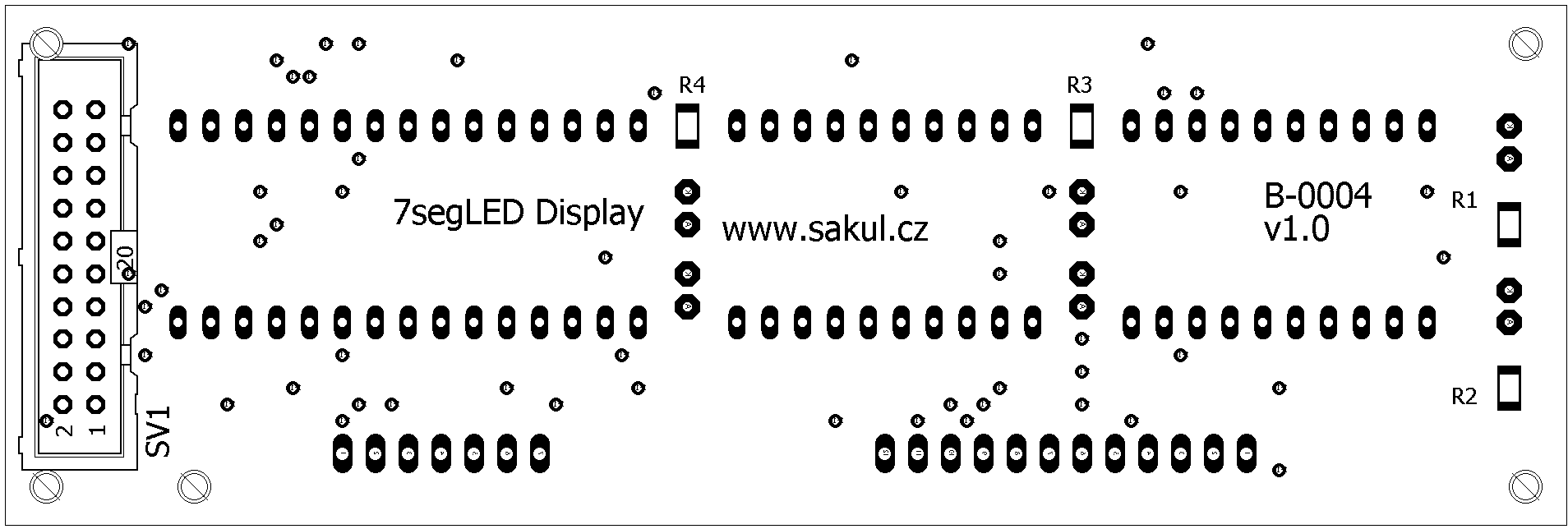
Assembly Plan - Display Board
Assembly Plan - Converter Board
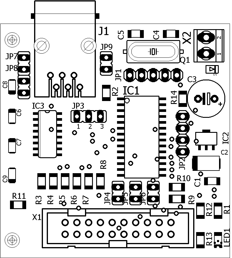
Careful assembly is required because most components are SMD and solder bridges can occur, especially around the processor. If the converter module will be used, fit a double-row female header instead of connector X2 on the processor board; the converter module is then inserted into it. On the display board, display DIS7 and connectors JP1 and JP2 are not fitted. PCB drawings are not shown here because both boards are double-sided with plated-through holes and cannot be practically manufactured from image documentation. Complete PCB documentation is included in the electronic documentation.
Bring-up and Settings
The device contains practically no adjustment elements, so with careful work it should operate on the first power-up. The prototype was built into a KM60 instrument enclosure with red plexiglass on the front. The processor board is inserted through connector holes in the rear panel and then screwed to the bottom of the box using suitable spacers so that the PCB remains horizontal and tightening the screws does not stress the connectors.
The only real setting is the choice of target switch contact type. Both NO and NC contacts can be used. Depending on the selected contacts, jumper JP4 must be fitted or left open. For NO contacts JP4 is fitted; for NC contacts JP4 is not fitted.
There are also jumpers JP1, JP2 and JP3. These jumpers ground the cathodes of the LEDs in the optocouplers. When fitted, the internal stopwatch supply can be used to power the target sensors from pin 1 of connectors J1-J4, which is especially useful with mechanical switches. To keep the stopwatch universal and compatible with any targets, the jumpers can also be left open and a separate power supply can be used for the target-side sensing circuit. The signals are then connected directly to the optocouplers, keeping the stopwatch fully isolated from the targets. The optocouplers reliably detect signal levels from 5 to 24 V. For other voltage levels, resistor values R1 to R3 must be changed. If the stopwatch is powered only from USB, the inputs may not work correctly with long target wires, therefore powering through connector US1 is recommended.
Processor Board Connector Pinout
| Connector | Description |
|---|---|
J1 | Left target stop |
J1-1 | Approx. +12 V output for external switches |
J1-2 | Signal input to optocoupler anode |
J1-3 | Signal input to optocoupler cathode, can be grounded through JP1 |
J1-4 | Negative voltage output |
J2 | Right target stop |
J2-1 | Approx. +12 V output for external switches |
J2-2 | Signal input to optocoupler anode |
J2-3 | Signal input to optocoupler cathode, can be grounded through JP2 |
J2-4 | Negative voltage output |
J3 | Start / split time / reset |
J3-1 | Approx. +12 V output for the external button |
J3-2 | Signal input to optocoupler anode |
J3-3 | Signal input to optocoupler cathode, can be grounded through JP3 |
J3-4 | Negative voltage output |
J4 | Combined connector |
J4-1 | Approx. +12 V output for external switches and button |
J4-2 | Signal input to OK1 anode, left target stop |
J4-3 | Signal input to OK1 cathode, can be grounded through JP1 |
J4-4 | Signal input to OK2 anode, right target stop |
J4-5 | Signal input to OK2 cathode, can be grounded through JP2 |
J4-6 | Signal input to OK3 anode, start / split time / reset |
J4-7 | Signal input to OK3 cathode, can be grounded through JP3 |
J4-8 | Negative voltage output |
The meaning and wiring of the remaining connectors is clear from the schematic. As an example, a control button can be connected to J3 by wiring one contact to J3-1, +12 V, and the second contact to J3-2, the optocoupler anode input. At this point the button would not work yet because the optocoupler cathode is not connected to any potential. Fitting JP3 grounds the OK3 cathode and the button can then apply voltage to the anode, switching the optocoupler on.
PC Communication
The device can be connected to a PC for displaying measured values and later analysis. There is currently no dedicated program for time management and editing; the operator must copy, store and process the data in suitable applications. The connection to the PC is made through a USB-B connector. Alternatively, an HC-06 wireless module inserted into JP6 can be used, but it must be configured before use. The configuration procedure is described in the HC-06 Bluetooth module guide.
A suitable program must be running on the PC to receive the data. The stopwatch is programmed so the exact PC program is not too critical, but it is optimized for HyperTerminal. This program was included in Windows XP and allowed measured data to be saved into a text file for later processing.
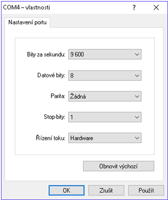
| Bits per second | 9600 |
|---|---|
| Data bits | 8 |
| Parity | none |
| Stop bits | 1 |
| Flow control | hardware |
The HyperTerminal setup example is shown above. To connect the stopwatch to a PC, the USB driver must also be installed. On Windows 10 this driver usually installs automatically through Device Manager. Older Windows versions require manual installation. The driver is included in the electronic documentation, or a CH340G driver can be found online. This is not needed when using an HC-06 Bluetooth module, but that module must be configured and paired with the PC.
The following video describes installation of the CH340G converter driver:
The next video shows how to find the PC port used for communication with the stopwatch:
The next video shows HyperTerminal setup for stopwatch communication. With this version, line wrapping no longer has to be configured:
Possible Issues
The device was designed with maximum emphasis on simple control and safety during non-professional handling. Therefore the power supply polarity does not matter and the device can even operate from AC voltage. The supply range is quite wide: 8-15 V. If the stopwatch is powered only through the USB connector, the inputs may not work correctly. This is not a fault, but a property of the design. To avoid this, power the stopwatch through connector US1 from an external supply.
Bill of Materials
The complete bill of materials is included in the electronic documentation available below.
Useful Links
| Stopwatch version with classic THT components | Fire Brigade Stopwatch PE11/2011 |
|---|---|
| CH340G driver installation | YouTube |
| Finding the USB/COM port on a PC | YouTube |
| Example of transferring times to PC | YouTube |
| THT construction description | YouTube |
Documentation - updated 2017-09-20
Finally, the complete build documentation can be downloaded here. It includes the Eagle project and the processor firmware.
Changes
2017-09-20 | SMD variant of this stopwatch was created. |
2015-06-20 | Stopwatch firmware updated to version 1.21B, which no longer requires line wrapping in HyperTerminal. A version that shows only final times and no split times was also added. |
2015-03-14 | Documentation and Eagle project updated; the web guide was updated as well. |
2015-03-13 | Video with USB-RS232 HL-340 driver installation was added. |
Configuration
__CONFIG _CP_ALL & _WDT_OFF & _BODEN_OFF & _PWRTE_ON & _XT_OSC & _WRT_OFF & _LVP_OFF & _CPD_ON
Bug Fixes
2013-04-16 - A bug with the first final time was fixed. Current program versions are 1.2A and 1.2B. More information is available in the bug-fix discussion.
Notice
This construction is original author work. It may not be copied to other websites or used commercially without the author's permission. Linking to this website and to this construction is allowed. I do not accept any responsibility for the device behaviour or for any damage caused by its use. The device is intended for personal use only. This construction uses microcontroller firmware that is subject to copyright. The program is licensed free of charge for personal use. Any sale is not allowed without the author's consent. Since I am not the author of this program, it is published here with the consent of its author, Botas.