For my small gantry CNC router I needed suitable control electronics. At first I tried the Arduino UNO + CNC Shield combination, but this solution turned out not to be suitable for my needs. I therefore decided to design my own electronics that would fully satisfy my requirements while keeping a reasonable price.
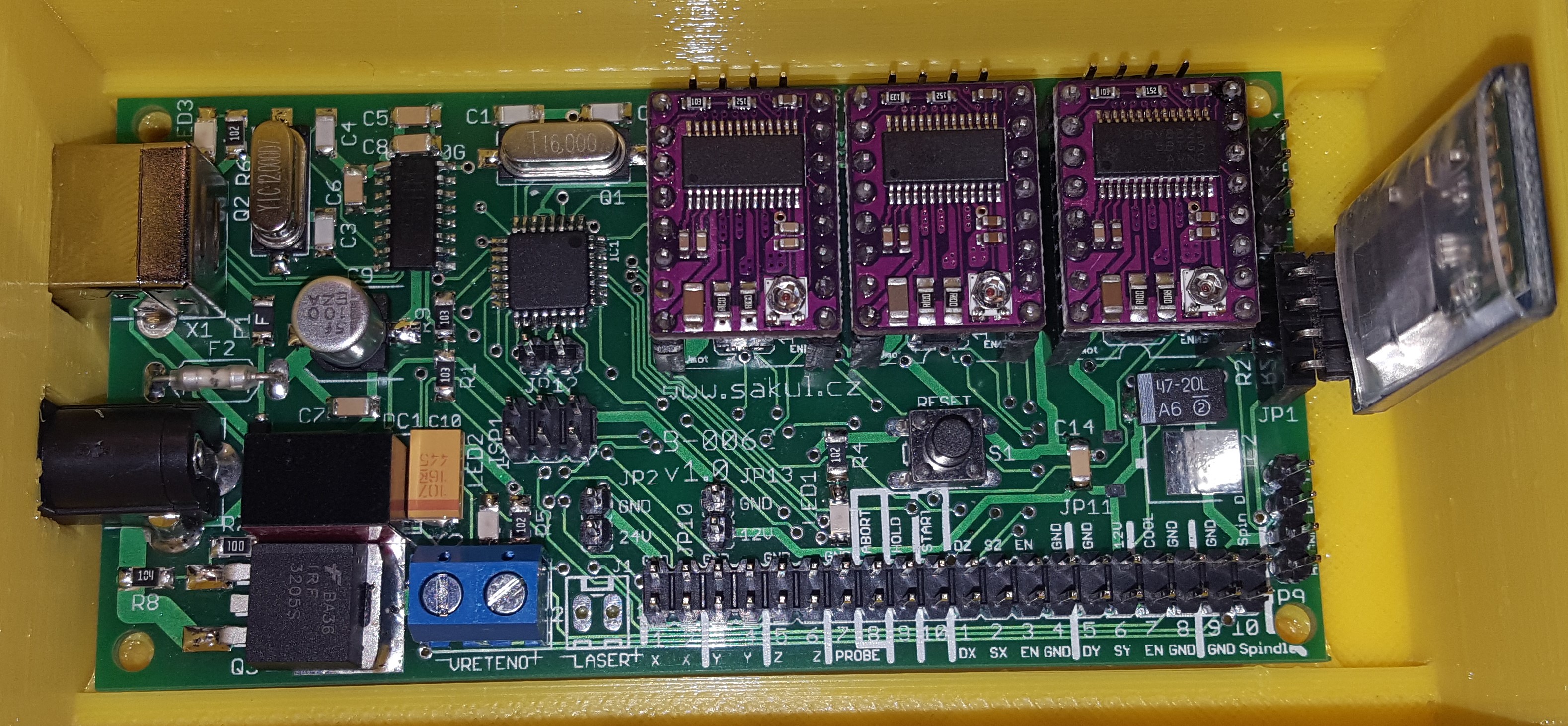
Technical Specifications
| Supply voltage | 12-24 V DC |
|---|---|
| Current consumption | approx. 4 A |
| PC connection | USB or Bluetooth |
| Communication speed | 115200 bps |
| Machine support | up to 3-axis CNC |
| Drivers | up to 2 A per driver, A4988, DRV8825 and similar modules |
| Microstepping | depending on driver up to 32, default 8 |
| Spindle | DC 12-24 V, laser can also be connected |
| Inputs | limit switches, control buttons and probe |
| Outputs | fan, external drivers, cooling and spindle or laser |
| Firmware | GRBL v0.9 or newer |
| Software | Candle, GrblPanel and others |
Device Description
As mentioned in the introduction, I designed this device to control my CNC router. I basically started from the recommended circuit and added several features. For example, wireless PC connection through an HC-06 Bluetooth module. I also added a power transistor for switching a DC spindle with speed-control capability and the option to connect a laser module. All inputs and outputs are brought out to pin headers, so external higher-power stepper drivers can also be connected to the electronics. Everything is controlled by an ATMEGA328P-AU processor running GRBL firmware v0.9 or newer, currently v1.1. The board connects to the computer either through USB or Bluetooth. When using USB, the BT module must be removed for communication to work correctly. Software such as Candle or GrblPanel can be used for control; GrblPanel is also suitable for firmware configuration. Many other supported programs exist, so everyone can choose what suits them best.
Schematic
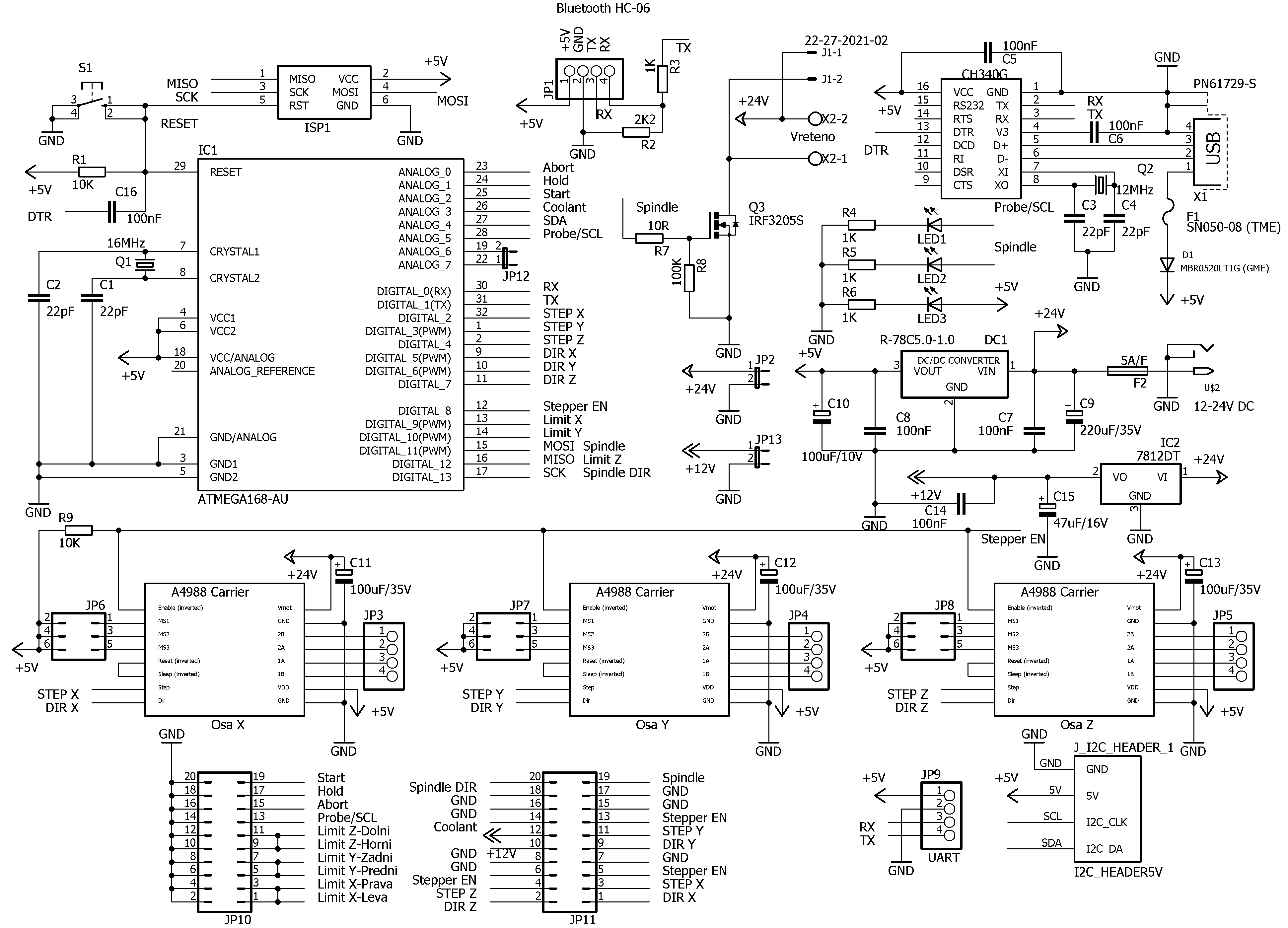
The schematic is relatively simple. The base is an ATMEGA328P-AU processor clocked at 16 MHz. A CH340G USB converter provides PC communication. The board can also be powered from USB, but only for the logic part. For full function, power must also be applied to connector US2, a DC 5/2.1 connector. A 5-6 A fuse follows the connector; its value is selected according to the used drivers, motors and spindle. The voltage is then stabilized to 12 V through IC2, useful for example for 12 V fans when powered from 24 V, and to 5 V through DC/DC converter DC1. Important parts of the board are the sockets for three stepper motor drivers. Many supported drivers can be used. JP6-JP8 set microstepping according to the selected driver. The ideal value for CNC use is 8 microsteps, which corresponds to jumpers fitted in positions 1 and 2. This setting is the same for all commonly used drivers.
The spindle or laser is switched through power MOSFET Q3 with a very low on-state resistance, so no cooling is required. The remaining part of the board consists of various connectors for peripherals such as limit switches. Everything is described in detail in the schematic, so connecting the peripherals should not cause any issues.
Assembly Plan
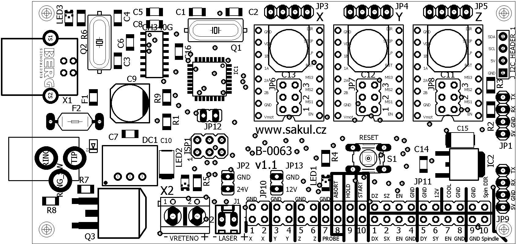
The whole board uses SMD assembly except for the connectors. Everything can be soldered comfortably with a soldering iron, including the processor. It is only necessary to work carefully and check that solder has not bridged pins and created a short circuit. It also often happens that one of the pins is forgotten and remains unsoldered. PCB drawings are not included here, but they are available in electronic form.
PCB Drawing
I do not include PCB drawings because this is a double-sided board with plated-through holes and manufacturing it from image documentation is not practical. The documentation at the end of the article contains the complete Eagle 7.7 project, from which the required production data can be exported.
Bring-up
After soldering all components, but before fitting the drivers, check for short circuits and verify that everything is soldered correctly. If everything is fine, connect 24 V supply voltage. Green LED3 should light up. Measure the current consumption; it should be below 30 mA. If it is higher, find and remove the cause. Fit jumpers on JP6-JP8 to positions 1 and 2, selecting 8 microsteps. It is important that jumpers in position 1 must always be fitted. Then measure the voltages on JP2, 24 V, JP13, 12 V, and JP9, 5 V. Only after everything is correct should you upload the bootloader to the processor. If you have a kit from me, this is not necessary because the processor is already programmed, including the latest firmware version. Connector ISP1 is used for this purpose. A suitable programmer is USBasp or whatever programmer you normally use. Upload the bootloader for the Arduino UNO board, ideally through Arduino IDE.
After the bootloader has been successfully uploaded, the firmware can be uploaded. This time connect the electronics board to the PC through USB. Upload the firmware using XLoader and select Arduino UNO or Sakul GRBL Board. The exact procedure then differs slightly depending on the PCB version:
PCB v1.0 (B-0062) - Press and hold the reset button on the board. Then click Upload in XLoader. At that moment release the reset button. After a short while the firmware should upload and the program should report success. If it fails, repeat the procedure until it works. The timing between pressing Upload and releasing reset must be matched.
PCB v1.1 (B-0063) - Simply click Upload in XLoader and wait for the upload to finish.
Once the firmware is uploaded, the electronics can be connected through control software. GrblPanel is ideal here because it can also conveniently perform the initial firmware-parameter configuration. A detailed guide is available in the GRBL firmware configuration article.
The last part is fitting and setting the drivers. Turn off the supply voltage first, and only then insert all three drivers. The correct orientation can be determined from the driver pin labels and the labels on the electronics board. Pin 1 is marked EN, Enable. The final step is current-limit adjustment using the small trimmer on each driver. Set the current slightly below the motor rating. For example, for 1.7 A motors set the current to 1.5 A. Driver current is determined by the reference voltage on the trimmer wiper against ground. Each driver uses a different formula for converting reference voltage to current, so consult the driver datasheet. It is also recommended to attach the small heatsinks supplied with the drivers to the driver chips. Be careful that the heatsink does not touch surrounding components.
At this point there is nothing preventing the motors and all other required peripherals from being connected and tested. The electronics can be installed into a box with a 40x40 mm fan opening placed directly above the drivers for ideal cooling.
Bill of Materials
The exact bill of materials including packages is available in the electronic documentation or in the PartList.
Useful Links
| Sakul CNC | Sakul CNC discussion |
|---|---|
| GRBL firmware configuration | GRBL configuration guide |
| GRBL firmware | GitHub GRBL wiki |
| Control software | Candle and others |
| DRV8825 and A4988 driver | DRV8825 |
Documentation
Finally, you can download the complete build documentation here. It includes the Eagle project and processor firmware.
Notice
This construction is original author work. It may not be copied to other websites or used commercially without the author's permission. Linking to this website and to this construction is allowed. I do not accept any responsibility for the device behaviour or for any damage caused by its use. The device is intended for personal use only. Any sale is not allowed without the author's consent.